Page 8
Setting Equipment
WARNING
Do not install the furnace on its front or its back. Do not
connect the return air ducts to the back of the furnace.
Doing so will adversely affect the operation of the safety
control devices, which could result in personal injury or
death.
The EL280UH gas furnace can be installed as shipped in
either the upow position or the horizontal position. Se-
lect a location that allows for the required clearances that
are listed on the unit nameplate. Also consider gas supply
connections, electrical supply, vent connection, and instal-
lation and service clearances [24 inches (610 mm) at unit
front]. The unit must be level.
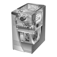
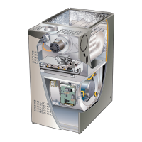
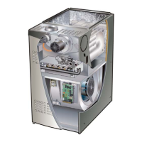
NOTE - Units with 1/3HP and 1/2HP blower motors are
equipped with three exible legs and one shipping leg. See
gure 6. In some units with 1/3HP blower motor, the ship-
ping leg is exible with rubber mounting grommets similar
to the other three mounting legs and require no modica-
tion. The rest of the units with 1/3HP and 1/2HP blower
motors (these blower motor housings will be tagged) have
a rigid shipping leg equipped with a shipping bolt and at
white plastic washer. The bolt and washer must be re-
moved before the furnace is placed into operation. Af-
ter the bolt and washer have been removed, the rigid leg
will not touch the blower housing.
RIGID LEG
(Remove shipping bolt
and washer)
Blower motor with three exible legs and one
rigid shipping leg. Blower motor housings
will be tagged for shipping bolt removal
FIGURE 6
Upow Applications
Allow for clearances to combustible materials as indicated
on the unit nameplate. Minimum clearances for closet or
alcove installations are shown in gure 7.
Upflow Application Installation Clearances
Top
Bottom
Left Side
Right Side
AIR FLOW
Type of Vent
Connector
Type C Type B1
Top 1 in. (25 mm) 1 in. (25 mm)
*Front 2-1/4 in. (57 mm)** 2-1/4 in. (57 mm)
Back 0 0
Sides 0† 0
Vent 6 in. (152 mm) 1 in. (25 mm)
Floor 0‡ 0‡
*Front clearance in alcove installation must be 24 in. (610 mm).
Maintain a minimum of 24 in. (610 mm) for front service access.
** 3-1/4 in. if single wall vent pipe is used.
‡For installation on a combustible floor, do not install the furnace
directly on carpeting, tile or other combustible materials other
than wood flooring.
†Left side requires 3 inches if a single wall vent is used on 14-1/2
inch
nets.
FIGURE 7
 Loading...