Page 8
I-UNIT COMPONENTS
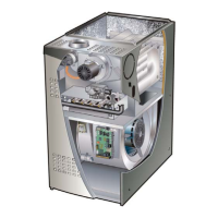
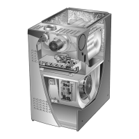
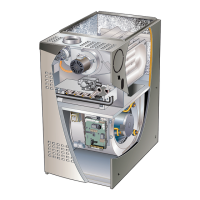
EL280UHE(X) unit components are shown in gure 1. The
gas valve, combustion air inducer and burners can be ac-
cessed by removing the access panel. Electrical compo-
nents are in the control box (gure 2) found in the blower
section.
EL280UHE(X) units are factory equipped with a bottom
return air panel in place. The panel is designed to be eld
removed as required for bottom air return. Markings are
provided for side return air and may be cut out in the eld.
ELECTROSTATIC DISCHARGE (ESD)
Precautions and Procedures
CAUTION
Electrostatic discharge can aect
electronic components. Take precautions
to neutralize electrostatic charge by
touching your hand and tools to metal
prior to handling the control.
A- Control Box
1. Control Transformer (T1)
A transformer located in the control box provides power to
the low voltage section of the unit. Transformers on all
models are rated 40VA with a 120V primary and a 24V
secondary.
2. Door Interlock Switch (S51)
A door interlock switch is wired in series with line voltage.
When the inner blower access panel is removed the unit
will shut down.
CONTROL BOX
Transformer
SureLight
®
Integrated Control
Interlock Switch
Circuit Breaker
Figure 2
3. Circuit Breaker (CB8)
A 24V circuit breaker is also located in the control box.
The switch provides overcurrent protection to the trans-
former (T1). The breaker is rated 3A at 32V. If the current
exceeds this limit the breaker will trip and all unit opera-
tion will shutdown. The breaker can be manually reset by
pressing the button on the face. See gure 3.
CIRCUIT BREAKER CB8
PRESS TO RESET
Figure 3
WARNING
Shock hazard.
Disconnect power before servicing. Integrated
control is not eld repairable. If control is inoperable,
simply replace entire control.
Can cause injury or death. Unsafe operation will
result if repair is attempted.
4. Integrated Control (A92)
Units are equipped with the SureLight® two-stage, inte-
grated control. The system consists of a ignition / blower
control (gures 4 and 5) with control pin designations in
tables 1 and 2 and ignitor. The control and ignitor work in
combination to ensure furnace ignition and ignitor durabil-
ity. The control provides gas ignition, safety checks and
indoor blower control with two-stage gas heating. The fur-
nace combustion air inducer, gas valve and indoor blower
are controlled in response to various system inputs such
as thermostat signal, pressure and limit switch signal and
ame signal. The control features a seven-segment LED
display, indicating furnace status and error codes. The
LED ashes in single digits. For example using table 4
under LIMIT CODE, an “E” followed by “2” followed by “5”
followed by “0”, the limit switch circuit is open. The control
also has two unpowered (dry) 1/4” contacts for a humid-
ier and a 120 volt accessory terminal. Both rated at (1)
one amp each.
Electronic Ignition
At the beginning of the heat cycle the integrated control
monitors the rst stage and second stage combustion air
inducer pressure switch. The control will not begin the
heating cycle if the rst stage pressure switch is closed
(bypassed). Likewise the integrated control will not be-
gin the second stage heating cycle if the second stage
pressure switch is closed, and will remain in rst stage
heat. However, if the second stage pressure switch closes
during the rst stage heat pre-purge, the control will allow
second stage heat. Once the rst stage pressure switch
is determined to be open, the combustion air inducer is
energized on low (rst stage) heat speed. When the dier-
ential in the pressure switch is great enough, the pressure
switch closes and a 15-second pre-purge begins.
 Loading...