Page 23
Intake Piping
The EL296DFV furnace may be installed in either direct
vent or non-direct vent applications. In non-direct vent ap-
plications, when intake air will be drawn into the furnace
from the surrounding space, the indoor air quality must be
considered. Guidelines listed in Combustion, Dilution and
Ventilation Air section must be followed.
Follow the next two steps when installing the unit in Direct
Vent applications, where combustion air is taken from out-
doors and ue gases are discharged outdoors. The pro-
vided air intake screen must not be used in direct vent
applications (outdoors).
1 - Use cement or a sheet metal screw to secure the
intake pipe to the inlet air connector.
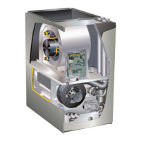
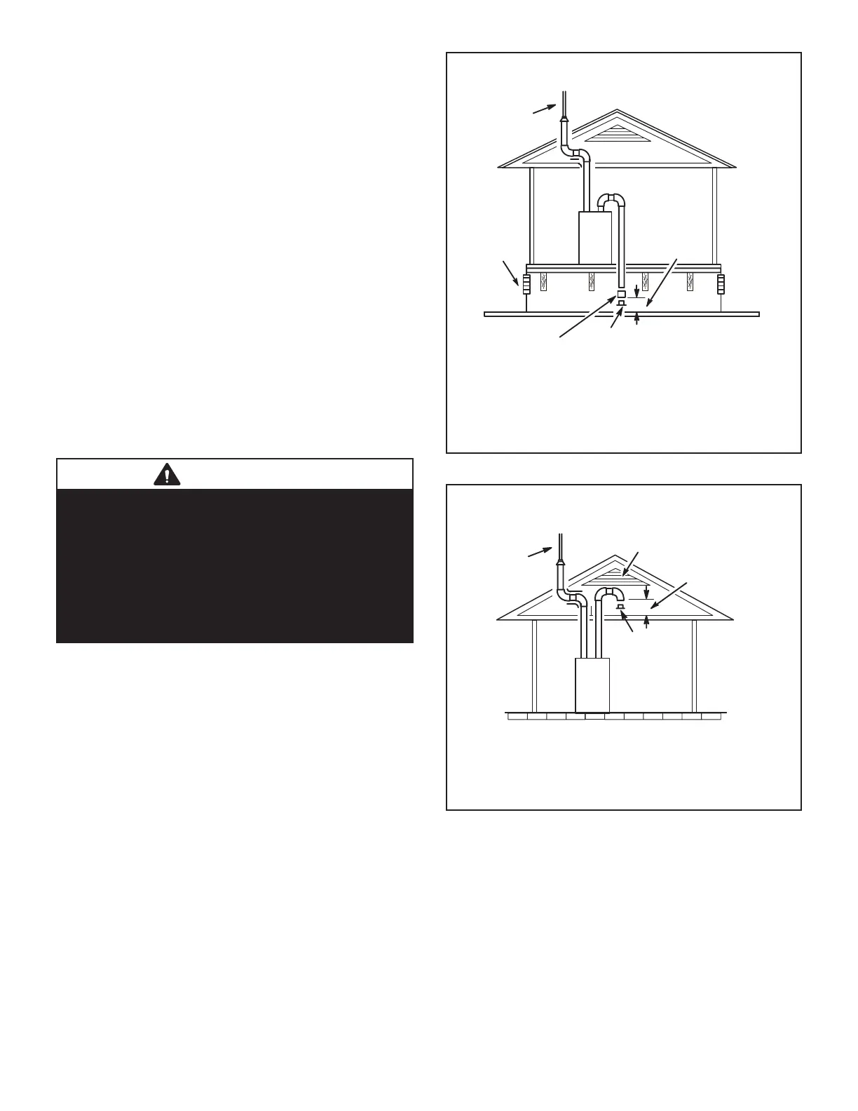
2 - If intake air is drawn from a ventilated crawlspace
(FIGURE 30) or ventilated attic (FIGURE 31) the
exhaust vent length must not exceed those listed
in table 9. If 3” diameter pipe is used, reduce to 2”
diameter pipe to accommodate the debris screen.
3 - Route piping to outside of structure. Continue with
installation following instructions given in general
guide lines for piping terminations and intake and
exhaust piping terminations for direct vent sections.
Refer to TABLE 7 for pipe sizes.
CAUTION
If this unit is being installed in an application with
combustion air coming in from a space serviced by an
exhaust fan, power exhaust fan, or other device which
may create a negative pressure in the space, take care
when sizing the inlet air opening. The inlet air opening
must be sized to accommodate the maximum volume
of exhausted air as well as the maximum volume of
combustion air required for all gas appliances serviced
by this space.
NOTE-The inlet and outlet air openings shall each have a free area
of at least one square inch per 4,000 Btu (645mm
2
per 1.17kW) per
hour of the total input rating of all equipment in the enclosure.
EQUIPMENT IN CONFINED SPACE
(Inlet Air from Ventilated Crawlspace and Outlet Air to Outside)
Roof Terminated
Exhaust Pipe
Furnace
Ventilation
Louvers
(Crawl space)
*Intake Debris Screen Provided)
Inlet Air
(Minimum
12 in.(305mm)
Above crawl
space floor)
Coupling or
3 in. to 2 in.
Transition
(Field Provided)
See table 8 for maximum vent lenghts
FIGURE 30
EQUIPMENT IN CONFINED SPACE
(Inlet Air from Ventilated Attic and Outlet Air to Outside)
NOTE-The inlet and outlet air openings shall each have a free area
of at least one square inch per 4,000 Btu (645mm
2
per 1.17kW) per
hour of the total input rating of all equipment in the enclosure.
Ventilation Louvers
Inlet Air
(Minimum
12 in.(305mm) Above
attic floor)
Roof Terminated
Exhaust Pipe
Furnace
*Intake Debris
Screen
(Provided)
See TABLE 8 for maximum vent lenghts
FIGURE 31

 Loading...