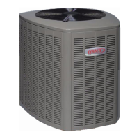
Do you have a question about the Lennox Elite XP13-030-230 and is the answer not in the manual?
Imperative to follow brazing technique to avoid damaging service valve seals.
Covers critical warnings and cautions regarding installation and service safety.
Compliance with Clean Air Act regarding refrigerant venting and disposal.
Explanation of the model number structure and its components.
Provides physical dimensions of the outdoor unit in inches and millimeters.
Diagram illustrating the arrangement of key plumbing, electrical, and sensor components.
Specifies recommended torque values for various caps and fasteners.
Details on using manifold gauge sets and operating service valves.
Procedures for opening, closing, accessing ports, and reinstalling caps.
Instructions for safely recovering HCFC-22 refrigerant from existing systems.
Notes on factors that may prevent full system charge recovery in Method 2.
Factors for unit placement, slab height, slope, and anchoring.
Procedures for elevating the unit or mounting it on a roof.
Guidance on slab and deck mounting, including stability brackets.
Advice on wind barriers and placement for roof-top installations.
Step-by-step guides for safely removing and correctly installing louvered panels.
Guidelines for adding oil, installing new/replacement line sets, and using existing ones.
Illustrations showing proper isolation for vertical and horizontal line set runs.
Critical warnings on moisture, fire hazards, hazardous materials, and rod types.
Steps for cutting lines, removing cores, and connecting the manifold gauge set.
Instructions for wrapping valves, brazing, and cooling the connections.
Steps for removing old metering devices and flushing the system.
Procedures for installing the expansion valve, sensing bulb, and equalizer line.
How to connect gauges and test the system for leaks using nitrogen.
Connecting gauges and evacuating the system to the required vacuum level.
Guidance on disconnect switches, wiring, and thermostat installation.
Schematic illustrating the unit's wiring connections and component labels.
Steps to verify connections, airflow, voltage, and refrigerant release.
Steps for units void of charge, including leak checking and refrigerant addition.
How to calculate total charge considering line set and weigh-in method.
Steps for optimizing charge using subcooling and adjusting indoor airflow.
Detailed steps for subcooling, including mode selection criteria.
Table of compatible units and their specific subcooling and charge requirements.
Tables for normal operating pressures and HFC-410A temperature vs. pressure.
Explanation of pressure switches (S4, S87) and compressor thermal protection (S173).
Description of defrost thermostat (S6), control (CMC1), and timing pins.
Features for compressor protection and troubleshooting the defrost control.
Interpretation of diagnostic LED sequences for troubleshooting.
Recommended maintenance tasks for both outdoor and indoor units by dealers.
Basic maintenance tasks homeowners can perform, such as filter checks.
Explains unique heat pump behaviors like defrost cycles and frost.
Steps to check before calling for service if the system fails to operate.
Fields for job details and checks for electrical, airflow, and refrigerant lines.
Checklist for verifying correct heating/cooling operation and thermostat settings.






 Loading...