Do you have a question about the Lennox XP19-024 and is the answer not in the manual?
Details nominal tonnage, connections, and refrigerant charge for XP19 units.
Provides line voltage, overcurrent protection, and circuit ampacity for XP19 models.
Lists optional accessories available for the XP19 series units.
Ensures proper system matching for warranty and operation, referencing Engineering Handbook.
Procedure for removing and reinstalling the main access panel.
Detailed steps for safely removing and installing louvered panels.
Illustrates the layout of major components in the XP19 unit.
Explains the design and operation of the two-stage scroll compressor.
Details how a scroll compressor compresses gas through orbiting scrolls.
Describes how bypass ports and a slider ring enable two-stage operation.
Procedure to verify compressor capacity stages using a thermostat and gauges.
Verifies 24VDC signal from LSOM to the compressor solenoid plug.
Checks the internal unloader solenoid resistance for proper operation.
Details bad/good solenoid checks and the function of the contactor.
Explains low/high pressure switches and compressor capacitor.
Describes the operation and internal workings of the variable speed fan motor.
Guidelines for applying line voltage and capacitor discharge safety.
Details normal motor rocking, soft-start, and shutdown features.
Steps to diagnose issues with the variable speed condenser fan motor.
Instructions for replacing the condenser fan motor.
Describes the filter drier's role in removing moisture and foreign matter.
Procedures for checking system dryness, acid, and foreign matter.
Explains the purpose of the accumulator in trapping liquid refrigerant.
Describes the LSOM module, its LEDs, and troubleshooting indications.
Explains connections for thermostat (Y2, L) and DC solenoid.
Procedures for verifying LSOM installation and resetting alert codes.
Details codes for Power, System Check, and Abnormal Conditions.
Explains fault and lockout codes for pressure, temperature, and electrical issues.
Details the defrost control board, its components, and diagnostic LEDs.
Explains pressure switch connections and the 5-strike lockout feature.
Describes the ambient, coil, and discharge sensors and their resistance values.
Provides resistance values for ambient, coil, and discharge sensors at various temperatures.
Illustrates the physical placement of ambient, coil, and discharge sensors.
Explains how ambient, coil, and discharge sensors detect faults and potential lockouts.
Details how defrost cycles are initiated, controlled, and terminated.
Procedure for initiating and performing defrost test cycles.
Explains how to interpret diagnostic LEDs for fault conditions.
Details how to activate test mode and its impact on unit operation.
Provides a flowchart for understanding defrost board test mode operations.
Diagram illustrating the sequence of events for board calibration.
Details how defrost cycles are initiated based on frost or time.
Explains LED states and their corresponding causes and solutions.
Details specific fault and lockout codes for pressure and sensor issues.
Describes the crankcase heater and its controlling thermostat.
Details refrigerant line sets and gauge manifold connections for charging.
Instructions for accessing Schrader ports and torque specifications for components.
Details the operation and front-seating of liquid and vapor line service valves.
Guidelines for adjusting R410A refrigerant charge based on line set length.
Steps for leak testing the system using nitrogen and R410A.
Procedure for evacuating the system to remove noncondensables and moisture.
Method for weighing in refrigerant charge, especially in cool weather.
Procedure for charging the unit using the subcooling method.
Provides normal operating pressures for heating and cooling stages.
Method to verify unit charge by comparing ambient and liquid line temperatures.
Guidelines for system service, recovery, and preventing moisture ingress.
Lists essential maintenance checks for the outdoor unit at the start of each season.
Schematic showing electrical connections for the XP19 heat pump outdoor unit.
Labels key components and their terminal connections on the wiring diagram.
Details first and second stage cooling operation, including capacity modulation.
Explains low and high capacity heating stages based on ambient temperature.
Describes how the system operates during a defrost cycle.
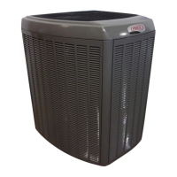
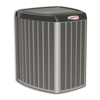
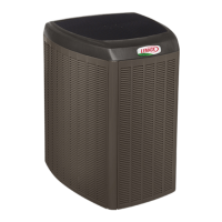
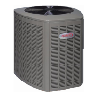
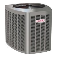
The Lennox XP19 is a high-efficiency residential split-system heat pump unit designed for heating and cooling applications. It features a two-step scroll compressor and uses R410A refrigerant. The unit is intended for use with an expansion valve in the indoor unit and is available in 2, 3, 4, and 5-ton sizes.
The XP19 operates on a two-stage modulated scroll compressor, which allows for smooth and continuous compression of gas. The compressor draws gas into crescent-shaped pockets formed by two scrolls, one stationary and one orbiting. As the orbiting scroll moves, the gas is forced toward the center, compressing it before discharge. This design provides efficient operation with fewer moving parts.
The unit incorporates a variable speed condenser fan motor, which adjusts its RPM to maintain constant airflow (CFM) and static pressure against the fan blade. This precise control of motor speed, achieved through pulse-width modulation, allows the motor to compensate for varying load conditions.
The XP19 utilizes a defrost control board that manages normal operation, calibration, and defrost cycles. In normal mode, the board monitors the O line, system operating mode (heat/cool), outdoor ambient temperature, coil temperature, and compressor run time to determine when a defrost cycle is needed. Calibration occurs after a defrost cycle to ensure no ice on the coil, establishing the temperature differential required for defrost. Defrost cycles are initiated based on frost detection (compressor runs longer than 34 minutes with a significant temperature difference between clear and frosted coil temperatures) or time (6 hours of heating mode compressor run time with coil temperature below 35°F).
A Lennox System Operation Monitor (LSOM) is integrated into the unit, providing diagnostic information through LED indicators. This 24-volt powered module helps troubleshoot system problems by indicating power status (GREEN), abnormal conditions (YELLOW flash codes), and thermostat demand without compressor operation (RED). The LSOM also manages the second-stage compressor solenoid output, energizing it when a Y2 call is received or when outdoor ambient temperature conditions warrant.
The XP19 is designed for residential use, providing both heating and cooling. Its two-step scroll compressor allows for efficient operation across different demand levels. The unit is charged with R410A refrigerant, and specific charging procedures are outlined for various line set lengths and outdoor ambient temperatures, using either the subcooling method or the approach method.
For charging, the system requires careful leak testing and evacuation to remove noncondensables and moisture, which can corrode internal components. The use of a thermocouple or thermistor electronic vacuum gauge calibrated in microns is recommended for accurate evacuation.
The unit's control system includes safety features such as a low pressure switch (S87) and a high pressure switch (S4) to protect the compressor from extreme operating conditions. These switches automatically reset and are ignored during initial startup, defrost, and specific temperature conditions to ensure proper operation.
Maintenance of the XP19 involves regular checks and procedures to ensure optimal performance and longevity. Key maintenance tasks include:
The defrost control board also includes diagnostic LEDs that indicate various operational conditions and fault codes, aiding in troubleshooting. These codes help identify issues such as power problems, sensor faults, low or high pressure faults, and circuit board failures. Resetting alert codes can be done manually by cycling 24VAC power to the LSOM or automatically when conditions return to normal.
The manual emphasizes that maintenance and service must be performed by a qualified installer or service agency to prevent property damage, personal injury, or loss of life. Electrical power must be disconnected before any service work to avoid shock hazards.
| Model | XP19-024 |
|---|---|
| Type | Heat Pump |
| Cooling Capacity (BTU) | 24000 |
| Cooling Capacity (tons) | 2 |
| Heating Capacity (BTU) | 24000 |
| Heating Capacity (tons) | 2 |
| SEER Rating | 19 |
| HSPF Rating | 10 |
| Refrigerant | R-410A |
| Compressor Type | Variable Speed |
| Stages | Variable |
| Voltage | 208/230 |
| Phase | 1 |
| Unit Weight (Outdoor) lbs | 220 |





 Loading...