Do you have a question about the Lennox XP19 and is the answer not in the manual?
Details the contents of the bag assembly for the outdoor unit, including bushings and isolation grommets.
Provides detailed measurements and diagrams for the outdoor unit's physical size and component layout.
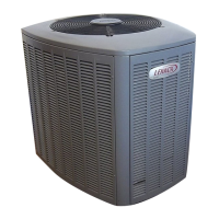
Introduces the XP19 Heat Pumps outdoor unit and its compatibility with HFC-410A refrigerant.
Provides guidance on following local codes and ensuring fasteners are tightened appropriately.
Details procedures for removing HCFC-22 refrigerant from existing systems using various methods.
Outlines the steps for safely disconnecting and removing the old outdoor unit from the installation site.
Details mandatory installation clearance requirements for the new outdoor unit.
Advises on placing the unit away from windows and on slabs, considering sound ordinances and drainage.
Explains how to remove panels and stabilize the unit on uneven surfaces using brackets.
Recommends line set sizes, lengths, and details isolation procedures for proper installation.
Provides step-by-step instructions and warnings for brazing the line set to the air conditioner unit.
Explains how to remove the existing HCFC-22 metering device for compatibility with HFC-410A systems.
Provides crucial instructions for flushing the system with refrigerant to remove contaminants, essential for warranty.
Describes the procedure for checking the system for refrigerant leaks using a leak detector.
Explains the critical process of evacuating the system to remove non-condensables and moisture.
Provides instructions for servicing units that are delivered without a refrigerant charge.
Details wiring requirements for supply voltage, grounding, thermostat, and low-voltage connections.
Covers testing system pressures, charging refrigerant, and checking indoor airflow for optimal performance.
Details the subcooling method for verifying the system's refrigerant charge accuracy.
Explains unit operation modes, thermostat functions, and the LSOM diagnostic module.
Provides guidance on interpreting LSOM LED codes for diagnosing system faults.
Describes the defrost control board, its sensors, and diagnostic LEDs for fault detection.
Details how defrost cycles are initiated, terminated, and how to use the test mode for diagnostics.
Lists essential maintenance checks and explains DCB diagnostic LEDs and fault codes.
Provides a procedure to verify the part- and full-load capacity operation of two-stage compressors.
Explains heat pump operation characteristics, thermostat functions, and preservice checks.
Provides field operational and start-up checklists for verifying system performance.