EasyManua.ls Logo

Lennox XP16 Series

Lennox XP16 Series
51 pages
To Next Page IconTo Next Page
Loading...
Page 1
2006 Lennox Industries Inc.
Corp. 0626−L5
Revised October 21, 2010
XP16
Service Literature
XP16 (HFC−410A) SERIES UNITS
WARNING
Improper installation, adjustment, alteration, service or
maintenance can cause personal injury, loss of life, or
damage to property.
Installation and service must be performed by a licensed
professional installer (or equivalent) or a service agency.
CAUTION
Physical contact with metal edges and corners while
applying excessive force or rapid motion can result in
personal injury. Be aware of, and use caution when
working near these areas during installation or while
servicing this equipment.
IMPORTANT
The Clean Air Act of 1990 bans the intentional venting of
refrigerant (CFCs, HCFCs and HFCs) as of July 1, 1992.
Approved methods of recovery, recycling or reclaiming
must be followed. Fines and/or incarceration may be
levied for noncompliance.
TABLE OF CONTENTS
Model Number Identification 2. . . . . . . . . . . . . . . . . . . .
Typical Serial Number Identification 2. . . . . . . . . . . . . .
Specifications 2. . . . . . . . . . . . . . . . . . . . . . . . . . . . . . . . .
Electrical Data 3. . . . . . . . . . . . . . . . . . . . . . . . . . . . . . . .
Unit Dimensions 4. . . . . . . . . . . . . . . . . . . . . . . . . . . . . .
Unit Parts Arrangement 5. . . . . . . . . . . . . . . . . . . . . . . .
Operating Gauge Set and Service Valves 7. . . . . . . . .
Recovering Refrigerant from System 9. . . . . . . . . . . . .
Unit Placement 10. . . . . . . . . . . . . . . . . . . . . . . . . . . . . . .
Removing and Installing Panels 12. . . . . . . . . . . . . . . . .
New or Replacement Line Set 14. . . . . . . . . . . . . . . . . .
Brazing Connections 16. . . . . . . . . . . . . . . . . . . . . . . . . . .
Flushing Line Set and Indoor Coil 19. . . . . . . . . . . . . . .
Installing Indoor Metering Device 20. . . . . . . . . . . . . . . .
Leak Test Line Set and Indoor Coil 21. . . . . . . . . . . . . .
Evacuating Line Set and Indoor Coil 22. . . . . . . . . . . . .
Electrical 23. . . . . . . . . . . . . . . . . . . . . . . . . . . . . . . . . . . . .
Servicing Units Void of Charge 24. . . . . . . . . . . . . . . . . .
Unit Start−Up 24. . . . . . . . . . . . . . . . . . . . . . . . . . . . . . . . . .
System Refrigerant 24. . . . . . . . . . . . . . . . . . . . . . . . . . . .
System Operation 36. . . . . . . . . . . . . . . . . . . . . . . . . . . . .
Defrost System 37. . . . . . . . . . . . . . . . . . . . . . . . . . . . . . .
Maintenance 44. . . . . . . . . . . . . . . . . . . . . . . . . . . . . . . . . .
Unit Wiring Diagram and Sequence of
Operations 46. . . . . . . . . . . . . . . . . . . . . . . . . . . . . . . . . . . . .
Checklists 51. . . . . . . . . . . . . . . . . . . . . . . . . . . . . . . . . . . .
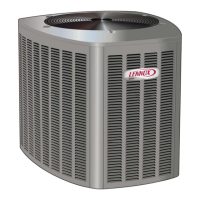
The XP16 is a high efficiency residential split−system
two−stage heat pump unit, which features a scroll
compressor and HFC−410A refrigerant. XP16 units are
available in 2, 3, 4 and 5 tons. tons. XP16 units are rated for
230 volts only. Applications where supply voltage is less
requires a hard start kit. The series is designed for use with
an indoor unit with an expansion valve approved for
HFC−410A.
WARNING
Electric Shock Hazard. Can cause injury or
death. Unit must be grounded in
accordance with national and local codes.
Line voltage is present at all components
when unit is not in operation on units with
single-pole contactors. Disconnect all
remote electric power supplies before
opening access panel. Unit may have
multiple power supplies.
Question and Answer IconNeed help?

Do you have a question about the Lennox XP16 Series and is the answer not in the manual?

Lennox XP16 Series Specifications

General IconGeneral
TypeHeat Pump
RefrigerantR-410A
StagesTwo-Stage
SEER RatingUp to 17.2
Compressor TypeScroll
Warranty5-Year Limited Warranty on compressor, 5-Year Limited Warranty on covered components. This product may be eligible for valuable 10-Year Limited Extended Warranty coverage with product registration.

Summary

Model Number Identification

Typical Serial Number Identification

Provides information on identifying the unit's serial number.

Specifications

Details the technical specifications of the XP16 series units.

Electrical Data

Unit Dimensions

Typical Unit Parts Arrangement

Operating Gauge Set and Service Valves

Torque Requirements

Lists the recommended torque values for various fasteners.

Using Manifold Gauge Set

Provides guidance on using a manifold gauge set with HFC-410A systems.

Operating Service Valves

Explains how to use the liquid and vapor line service valves for system operations.

Service Valves Angle and Ball

Operating Angle Type Service Valve

Details the procedure for operating angle type service valves.

Operating Ball Type Service Valve

Details the procedure for operating ball type service valves.

Accessing Service Ports

Explains how to access the service port and reconnect caps.

Reinstalling Stem Caps

Describes how to properly reinstall stem caps for service valves.

Recovering Refrigerant from System

Unit Placement

Positioning Considerations

Factors to consider when positioning the outdoor unit for optimal performance and sound.

Placing Unit on Slab

Guidance on installing the unit on a ground-level slab.

Elevating the Unit

Instructions for raising the unit using support feet extenders.

Stabilizing Unit on Uneven Surfaces

Roof Mounting

Guidelines for mounting the unit on a roof, including clearance and wind barriers.

Removing and Installing Panels

Louvered Panel Removal and Installation

Louvered Panel Removal

Procedure for safely removing the louvered panels from the unit.

Louvered Panel Installation

Procedure for correctly reinstalling the louvered panels onto the unit.

New or Replacement Line Set

Line Set Isolation

Brazing Connections

Flushing Line Set and Indoor Coil

Flushing Line Set

Procedure for flushing the line set and indoor coil with refrigerant.

Installing Indoor Metering Device

Indoor Expansion Valve Installation

Instructions for installing the indoor expansion valve.

Sensing Bulb Installation

Guidance on correctly mounting and insulating the sensing bulb.

Equalizer Line Installation

Procedure for connecting the equalizer line to the expansion valve.

Leak Test Line Set and Indoor Coil

Test for Leaks

Procedure for testing the line set and indoor unit connections for leaks.

Evacuating Line Set and Indoor Coil

Evacuate the System

Steps for evacuating the system to an absolute pressure of 500 microns.

Electrical

Circuit Protection and Wiring

Guidance on sizing circuits, installing disconnect switches, and wiring.

24 VAC Transformer

Information on using the provided 24VAC transformer for control power.

Thermostat Installation

Recommendations for installing the room thermostat.

Low Voltage Connections

Details on making 24VAC control wire connections to the unit.

Servicing Units Void of Charge

Unit Start-Up

Procedure for starting up the unit after servicing or when void of charge.

System Refrigerant

Procedures for connecting gauges, checking airflow, and adjusting refrigerant.

Charging Information (Models XP16-XXX-230-01 & -02)

Weigh-in Method

Procedure for charging the unit using the weigh-in method.

Subcooling Method

Procedure for charging the unit using the subcooling method.

PressuresApproach Method

Procedure for charging using normal operating pressures and approach.

Operating Pressures Table

Reference table for normal operating pressures under various conditions.

Charging Information (Models XP16-XXX-230-03, -04, -05)

Adding or Removing Refrigerant

Guidance on adding or removing refrigerant for specific models.

Cooling Mode Indoor Airflow

Procedure to adjust for optimal airflow across the indoor coil in cooling mode.

Heating Mode Indoor Airflow

Method to calculate blower airflow (CFM) in heating mode.

Weigh-In Charging Method

Calculating System Charge

Steps to calculate the total refrigerant charge for an empty system.

Subcooling Charging Method

Using Cooling Mode

Procedure for subcooling charge in cooling mode.

Using Heating Mode

Procedure for subcooling charge in heating mode.

System Operation

Second-Stage Operation

How the second-stage compressor operates in heating and cooling.

Thermostat Operation

Information regarding thermostat requirements and functions.

Emergency Heat

Details on the emergency heat function and its application.

Filter Drier

Information about the unit's filter drier and replacement.

Defrost System

Defrost System Description

Overview of the defrost system and controller components.

Pressure Switch Operation

Details connections, settings, and lockout conditions for pressure switches.

Temperature Sensors

Explains sensor types, locations, and their role in defrost operation.

Sensor Faults and Lockouts

Coil Sensor Operation

Coil sensor function, fault conditions, and resistance values.

High Discharge Line Sensor

Discharge sensor function, faults, and lockout codes.

Defrost Control Settings

Describes shunt settings, delay mode, and operational modes.

Test Mode Operation

Explains how to initiate test events using jumpers.

Defrost Cycle Logic

Frost Detection Initiation

How the system initiates defrost based on frost accumulation.

Time-Based Defrost Initiation

How time elapsed triggers a defrost cycle.

Defrost Actuation and Termination

Conditions for initiating, holding, and ending a defrost cycle.

Test Mode

Defrost Board Diagnostic LEDs

Outdoor Fan Motor

Blower Motor Components

Identifies the key components of the blower motor assembly.

Internal Operation

Explains the operation of the variable speed condenser fan motor.

Initial Power Up

Describes the power-up sequence and potential issues for the motor.

Outdoor Fan Motor Operations

Motor Start-Up

Details the motor's start-up process and safety features.

Troubleshooting

Troubleshooting steps for when the variable speed fan motor does not energize.

Replacement

Instructions for replacing the fan motor, including shaft mounting.

Two-Stage Modulation Compressor Checks

Maintenance

General maintenance checks to be performed on the system.

System Maintenance

Outdoor Unit Maintenance

Cleaning and inspection procedures for the outdoor unit and coil.

Outdoor Coil Care

Specific cleaning advice for outdoor coils, especially in coastal environments.

Indoor Unit Maintenance

Checks and cleaning procedures for the indoor unit components.

Unit Wiring Diagrams and Sequence of Operations

Sequence of Operation

Cooling Operation

Details the sequence of operation for cooling modes.

Heating Operation

Details the sequence of operation for heating modes.

Defrost Mode Operation

Checklists

Two-Stage Modulation Compressors Field Operational Checklist

Checklist for evaluating compressor field operational performance.

XP16 Start-Up and Performance

Checklist for initial start-up and performance verification of the XP16 unit.

Related product manuals