Page 4
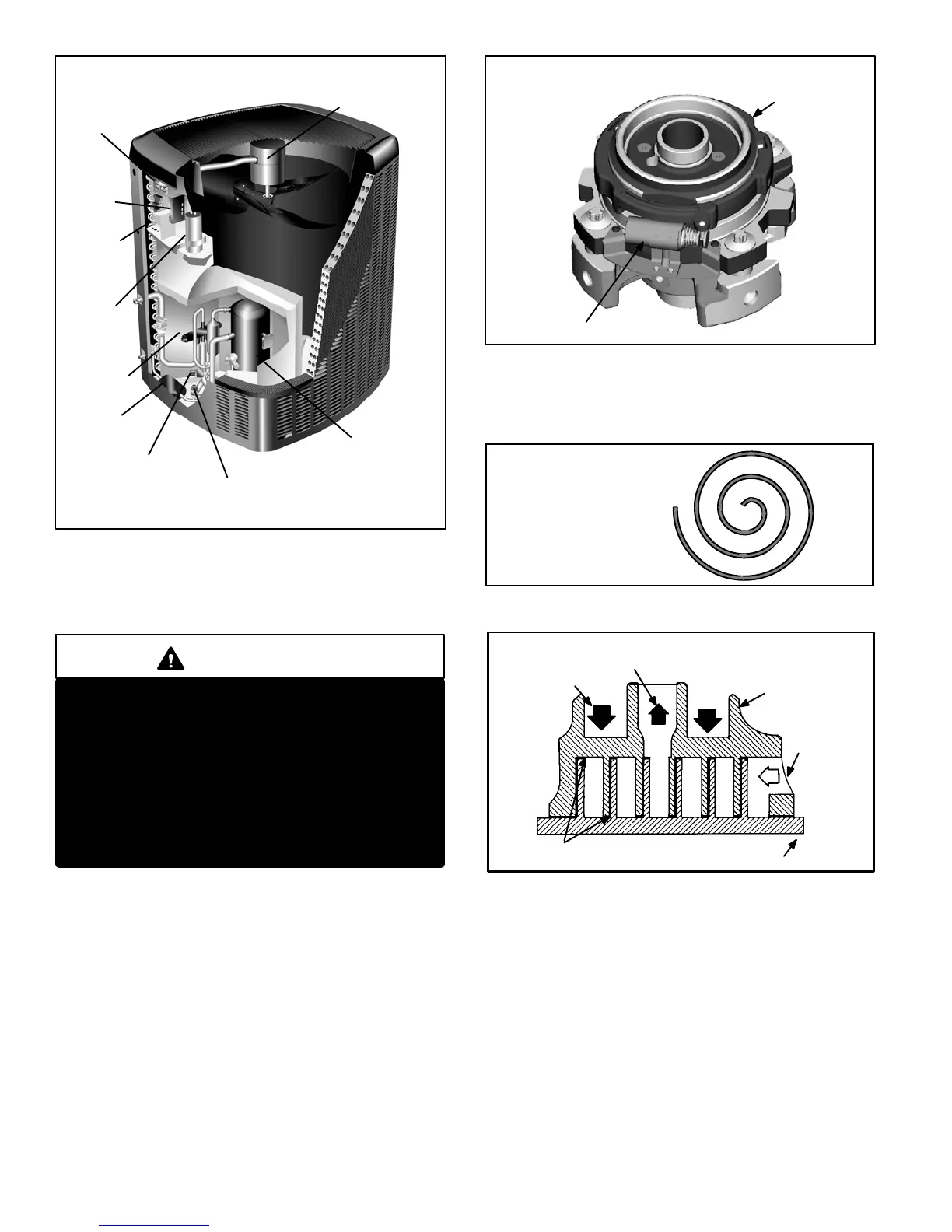
FIGURE 3
XP19 PARTS ARRANGEMENT
OUTDOOR FAN
COMPRESSOR
CONTACTOR
DEFROST
CONTROL
LSOM
LOW PRESSURE
SWITCH
HIGH PRESSURE
SWITCH
DRIER
REVERSING
VALVE
CAPACITOR
ELECTROSTATIC DISCHARGE (ESD)
Precautions and Procedures
CAUTION
Electrostatic discharge can affect electronic
components. Take precautions during unit instal-
lation and service to protect the unit’s electronic
controls. Precautions will help to avoid control
exposure to electrostatic discharge by putting
the unit, the control and the technician at the
same electrostatic potential. Neutralize electro-
static charge by touching hand and all tools on an
unpainted unit surface before performing any
service procedure.
A−Two−Stage Scroll Compressor (B1)
The scroll compressor design is simple, efficient and re-
quires few moving parts. A cutaway diagram of the scroll
compressor is shown in figure 1.The scrolls are located in
the top of the compressor can and the motor is located just
below. The oil level is immediately below the motor.
The scroll is a simple compression concept centered
around the unique spiral shape of the scroll and its inherent
properties. Figure 5 shows the basic scroll form. Two iden-
tical scrolls are mated together forming concentric spiral
shapes (figure 6). One scroll remains stationary, while the
other is allowed to orbit" (figure 7). Note that the orbiting
scroll does not rotate or turn but merely orbits" the station-
ary scroll.
FIGURE 4
TWO−STAGE MODULATED SCROLL
slider ring
solenoid actuator coil
FIGURE 5
SCROLL FORM
FIGURE 6
STATIONARY
SCROLL
ORBITING SCROLL
DISCHARGE
SUCTION
CROSS−SECTION OF SCROLLS
TIPS SEALED BY
DISCHARGE PRESSURE
DISCHARGE
PRESSURE
The counterclockwise orbiting scroll draws gas into the out-
er crescent shaped gas pocket created by the two scrolls
(figure 7 − 1). The centrifugal action of the orbiting scroll
seals off the flanks of the scrolls (figure 7 − 2). As the orbiting
motion continues, the gas is forced toward the center of the
scroll and the gas pocket becomes compressed (figure 7
−3). When the compressed gas reaches the center, it is dis-
charged vertically into a chamber and discharge port in the
top of the compressor (figure 7 − 4). The discharge pressure
forcing down on the top scroll helps seal off the upper and
lower edges (tips) of the scrolls (figure 6). During a single or-
bit, several pockets of gas are compressed simultaneously
providing smooth continuous compression.