Page 19
K−Crankcase Heater (HR1)
Compressors in all units are equipped with a 70 watt belly-
band type crankcase heater. HR1 prevents liquid from ac-
cumulating in the compressor. HR1 is controlled by the
crankcaseheater thermostat.
L− Crankcase heater Thermostat (S40)
Thermostat S40 controls the crankcase heater in all units.
S40 is located on the liquid line. When liquid line tempera-
ture drops below 50° F the thermostat S40 closes energizing
HR1. The thermostat will open, de−energizing HR1 once liq-
uid line temperature reaches 70° F .
III−REFRIGERANT SYSTEM
IMPORTANT
The Clean Air Act of 1990 bans the intentional vent-
ing of (CFC’s and HFC’s) as of July 1, 1992. Approved
methods of recovery, recycling or reclaiming must
be followed. Fines and/or incarceration my be levied
for noncompliance.
Field refrigerant piping consists of liquid and vapor lines
from the outdoor unit (sweat connections). Use Lennox
L15 series line sets as shown in table 7.
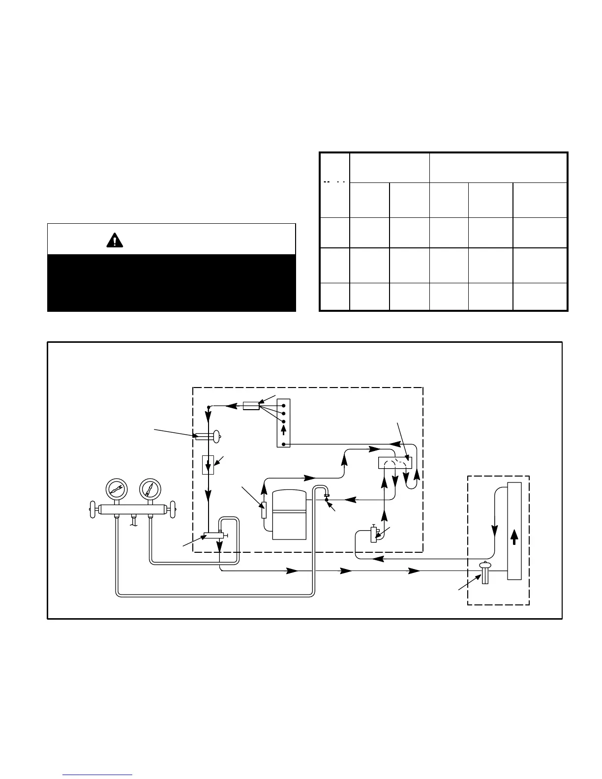
Separate liquid and suction service ports are provided at
the service valves for connection of gauge manifold during
charging procedure. Figure 20 shows XP19 refrigerant
flow and gauge manifold connections.
TABLE 7
Valve Field Size
Connections
Recommended Line Set
Model
Liquid
Line
Vapor
Line
Liquid
Line
Vapor
Line
L15
Line Sets
−024,−
036
3/8 in.
10 mm
7/8 in.
22 mm
3/8 in.
10 mm
7/8 in.
19 mm
L15−65
15 ft. − 50 ft.
4.6 m − 15 m
−048
3/8 in.
10 mm
1−1/8 in.
29 mm
3/8 in.
10 mm
7/8 in.
22 mm
L15−65
15 ft. − 50 ft.
4.6 m − 15 m
−060
3/8 in.
10 mm
1−1/8 in.
29 mm
3/8 in.
10 mm
1−1/8 in.
29 mm
Field
Fabricated
XP19 COOLING CYCLE
(Showing Gauge Manifold Connections)
NOTE−Use gauge ports on vapor line valve and liquid valve for evacuating refrigerant lines
and indoor coil. Use suction gauge port to measure suction pressure during charging.
OUTDOOR
COIL
EXPANSION/
CHECK VALVE
BIFLOW
FILTER / DRIER
TO
R410A
DRUM
LOW
PRESSURE
HIGH
PRESSURE
COMPRESSOR
REVERSING VALVE
VAPOR
LINE
VALVE
MUFFLER
NOTE − ARROWS INDICATE
DIRECTION OF REFRIGERANT FLOW.
REFRIGERANT WILL FLOW IN OPPOSITE
DIRECTION IN HEATING CYCLE.
SERVICE
PORT
SUCTION
EXPANSION/CHECK
VALVE
INDOOR UNIT
OUTDOOR UNIT
LIQUID
LINE
SERVICE
PORT
GAUGE MANIFOLD
DISTRIBUTOR
INDOOR
COIL
FIGURE 20

 Loading...


