Page 9
Initial Power Up
When line voltage is applied to the motor, there will be a
large inrush of power lasting less than 1/4 second. This in-
rush charges a bank of DC filter capacitors inside the con-
troller. If the disconnect switch is bounced when the discon-
nect is closed, the disconnect contacts may become
welded. Try not to bounce the disconnect switch when ap-
plying power to the unit.
The DC filter capacitors inside the controller are connected
electrically to the speed tap wires. The capacitors take
approximately 5 minutes to discharge when the disconnect
is opened. For this reason it is necessary to wait at least 5
minutes after turning off power to the unit before attempting
to service motor.
DANGER
Disconnect power from unit and wait at
least five minutes to allow capacitors
to discharge before attempting to ser-
vice motor. Failure to wait may cause
personal injury or death.
Motor Start-Up
At start-up, the motor may gently rock back and forth for a
moment. This is normal. During this time the electronic
controller is determining the exact position of the rotor.
Once the motor begins turning, the controller slowly
eases the motor up to speed (this is called soft-start").
The motor may take as long as 10-15 seconds to reach
full speed. If the motor does not reach 200rpm within 13
seconds, the motor shuts down. Then the motor will im-
mediately attempt a restart. The shutdown feature pro-
vides protection in case of a frozen bearing or blocked
fan blade. The motor may attempt to start eight times. If
the motor does not start after the eighth try, the controller
locks out. Reset controller by momentarily turning off
power to unit.
Troubleshooting
If first or second stage thermostat call for cool is present
and the variable speed condenser fan motor does not ener-
gize, check voltage at the breaker box. If voltage is present
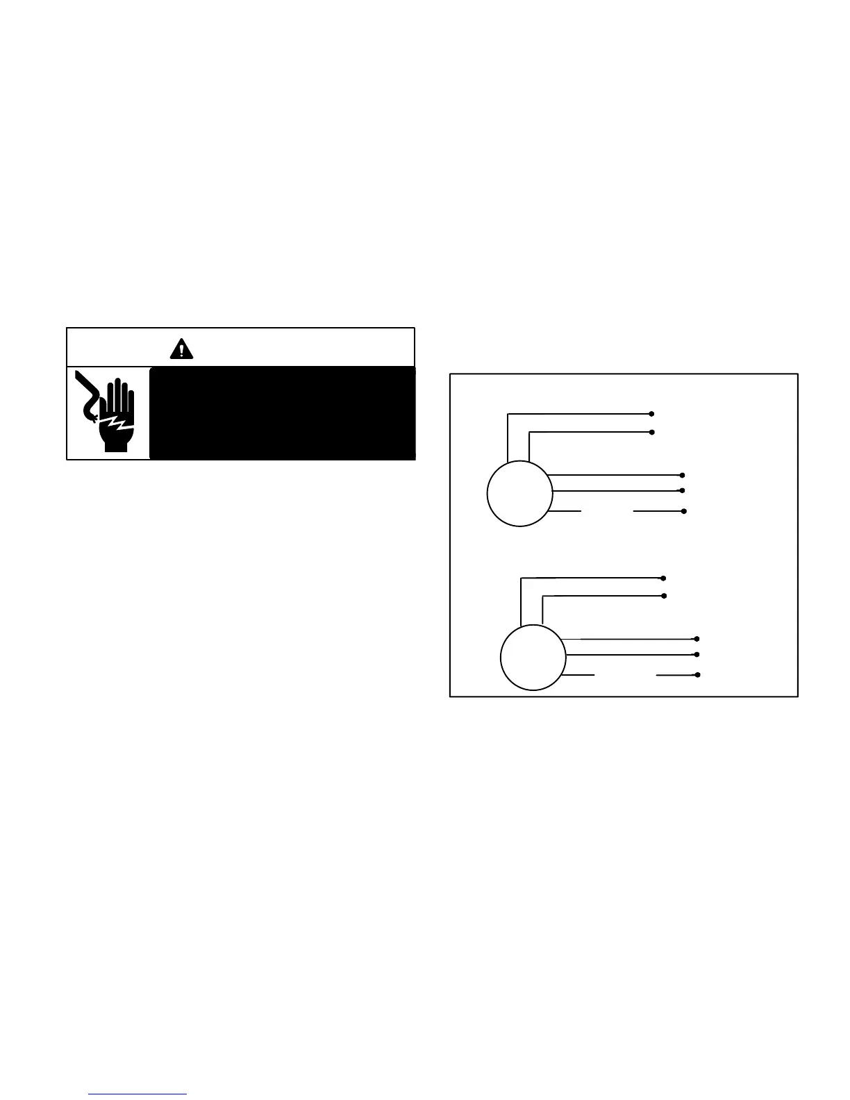
do the following and reference figure 12.
1− Check for 240 volts between the compressor RED wi-
res.
2− Initiate a first stage call for cool. Check for 24 volts be-
tween the fan motor YELLOW wire and fan motor
BLACK wire.
3− Initiate a second stage call for cool. Check for 24 volts
between the fan motor YELLOW wire and fan motor
BLACK wire, then check for 24 volts between the fan
motor BLUE wire and fan motor BLACK.
4− Repeat steps 1 and 2 with a HEAT call.
FIGURE 12
RED
RED
240V
YELLOW
BLUE
BLACK
common
1st Stage (low capacity − 700 rpm)
2nd Stage (High capacity − 820 rpm)
B4
24V
Y1
Y2
RED
RED
YELLOW
BLUE
BLACK
B4
240V
24V
common
Y2
Y1
24V
0V
24V
24V
240V
240V