Page 8
Bad Solenoid
a. Measure the resistance at the 2−pin fusite. The resist-
ance should be 32 to 60 ohms depending on compressor
temperature. If no resistance replace compressor.
b. Measure the resistance from each fusite pin to
ground. There should not be continuity to ground. If so-
lenoid coil is grounded, replace compressor.
Good Solenoid
a. Seals not shifting, replace compressor
b. Slider ring not shifting, replace compressor.
B−Contactor (K1)
The compressor is energized by a contactor located in the
control box. All XP19 units are single phase and use single−
pole contactors.
C−Low Pressure Switch (S87)
The XP19 is equipped with an auto−reset low pressure
switch which is located on the suction line. The switch shuts
off the compressor when the suction pressure falls below
the factory setting. This switch is ignored during the first 90
seconds of compressor start up, during defrost operation,
90 seconds after defrost operation, during test mode and
when the outdoor temperature drops below 15°F.
The switch closes when it is exposed to 55 psig and opens
at 25 psig. It is not adjustable.
D−High Pressure Switch (S4)
IMPORTANT
Pressure switch settings for R410A refrigerant will
be significantly higher than units with R22.
An auto-reset, single-pole/single-throw high pressure switch
is located in the liquid line. This switch shuts off the compres-
sor when liquid line pressure rises above the factory setting.
The switch is normally closed and is permanently adjusted to
trip (open) at 590 +
15 psi and close at 418 + 15 psi. See fig-
ure 3 for switch location.
E−Capacitor (C12)
The compressor in XP19−024, −036, −048 and −060 units
use a permanent split capacitor (see unit wiring diagram).
The capacitor is located inside the unit control box. Ratings
are on capacitor side.
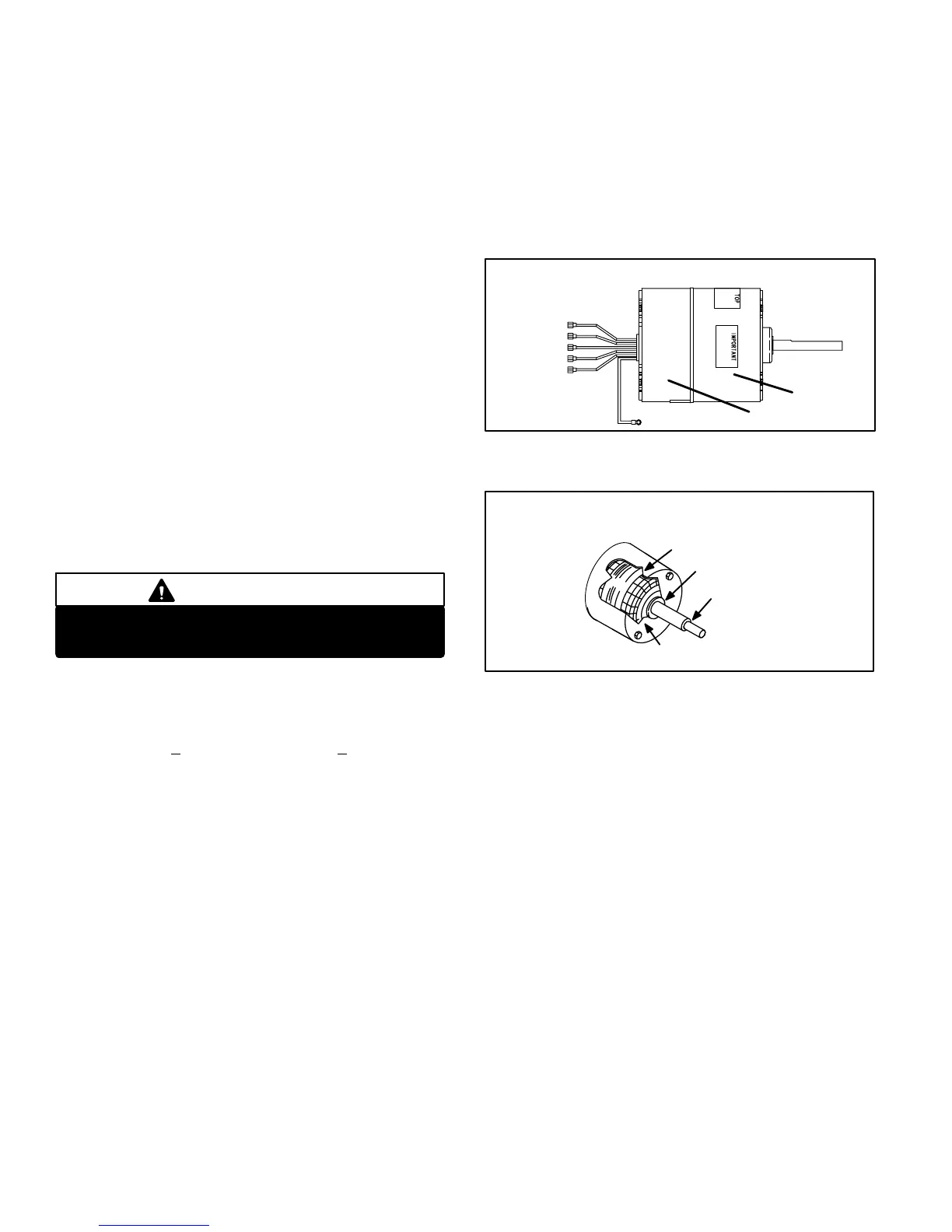
F−Condenser Fan with
Variable Speed Motor(B4)
The variable speed condenser fan motor (figure 10) used in all
units is a three-phase, electronically controlled d.c. brushless
motor (controller converts single phase a.c. to three phase
d.c.), with a permanent-magnet-type rotor, manufactured by
GE. Because this motor has a permanent magnet rotor it does
not need brushes like conventional D.C. motors. The motors
consist of a control module and motor . Internal components
are shown in figure 11. The stator windings are split into three
poles which are electrically connected to the controller. This ar-
rangement allows motor windings to be turned on and off in
sequence by the controller.
The controller is primarily an a.c. to d.c. converter. Con-
verted d.c. power is used to drive the motor. The control-
ler contains a microprocessor which monitors varying
conditions inside the motor (such as motor workload).
The controller uses sensing devices to know what position
the rotor is in at any given time. By sensing the position of
the rotor and then switching the motor windings on and off
in sequence, the rotor shaft turns the blower.
VARIABLE SPEED CONDENSER FAN MOTOR
FIGURE 10
RED
YELLOW
BLACK
RED
BLUE
motor
control module
BLOWER MOTOR COMPONENTS
FIGURE 11
STATOR
(WINDINGS)
OUTPUT
SHAFT
BEARING
ROTOR
Internal Operation
The condenser fan motor is a variable speed motor with RPM
settings at 700 (Y1) and 820 (Y2). The variation in speed is
accomplished each time the controller switches a stator wind-
ing (figure10) on and off, it is called a pulse." The length of
time each pulse stays on is called the pulse width." By vary-
ing the pulse width the controller varies motor speed (called
pulse-width modulation"). This allows for precise control of
motor speed and allows the motor to compensate for varying
load conditions as sensed by the controller. In this case, the
controller monitors the static workload on the motor and var-
ies motor rpm in order to maintain constant airflow (cfm).
Motor rpm is continually adjusted internally to maintain
constant static pressure against the fan blade. The control-
ler monitors the static work load on the motor and motor
amp-draw to determine the amount of rpm adjustment.
Blower rpm is adjusted internally to maintain a constant
cfm. The amount of adjustment is determined by the incre-
mental taps which are used and the amount of motor load-
ing sensed internally. The motor constantly adjusts rpm to
maintain a specified cfm.