Page 7
TABLE 1
Compressor Operation
Unit Readings
Y1 −
1st-Stage
Expected Results
Y2 −
2nd-Stage
Compressor
Voltage Same
Amperage Higher
Condenser Fan motor
Amperage Same or Higher
Temperature
Ambient Same
Outdoor Coil Discharge Air Higher in Cooling
Lower in Heating
Compressor Discharge Line Higher
Indoor Return Air Same
Indoor Coil Discharge Air Lower in Cooling
Higher in Heating
Pressures
Suction (Vapor) Lower
Liquid Higher
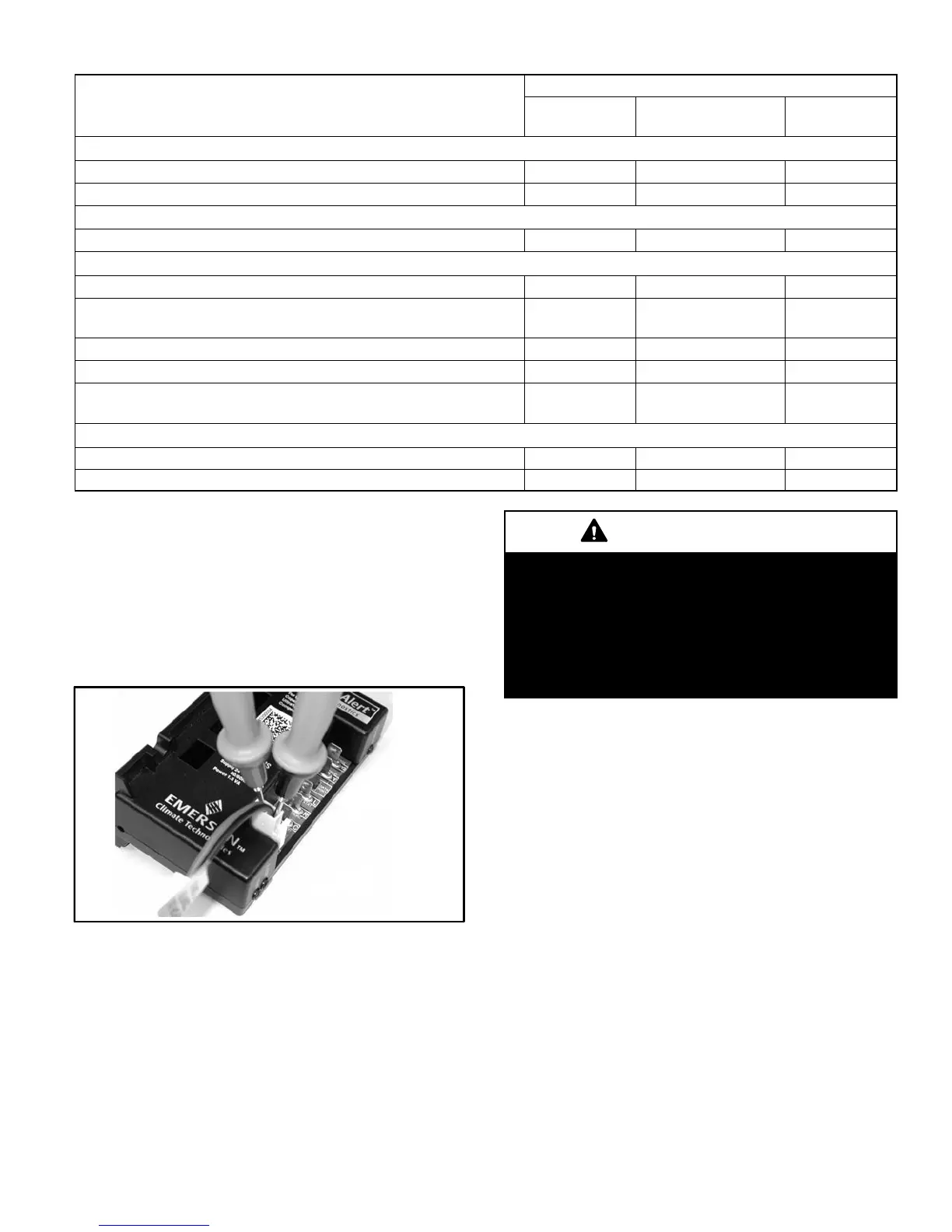
STEP 2 Confirm DC voltage output on compressor
solenoid plug
1−. Shut power off to the outdoor unit.
2−. Insert lead wires from voltmeter into back of the red
and black wire plug jack that feeds power to compres-
sor solenoid coil. Set voltmeter to DC volt scale to read
DC voltage output from LSOM II plug. See figure 9.
FIGURE 9
3−. Apply a Y1 and Y2 demand from the indoor thermostat
to the LSOM II.
4−. Turn power back on to unit.
5−. Compressor should cycle ON" when Y1 is calling.
6−. With Y2 calling, 5 seconds after compressor cycles
ON", LSOM II will output 24 volt DC signal to the com-
pressor solenoid plug. Once the solenoid has pulled in,
the LSOM II will reduce the DC voltage to a pulsating
6 to 18 volt DC output to the solenoid to allow the sole-
noid to remain energized.
IMPORTANT
When checking compressor for two−stage operation,
always cycle Y1 to Y2 from terminals on the LSOMII
or room thermostat connections. DO NOT cycle sec-
ond stage (Y2) of compressor by unplugging the
24VDC solenoid LSOM II end of plug. The LSOM II will
only output a 6 to 18VDC signal which will be insuffi-
cient voltage to pull the solenoid coil in for second
stage.
If compressor solenoid is still not shifting to high capac-
ity, this check will verify that DC power is being fed from
the LSOM II.
7−. Shut power off to unit (main and low voltage)
8−. Unplug the 2 pin solenoid plug from the fusite connec-
tion on the compressor and the plug end from the
LSOM II.
9−. Using an OHM meter, check for continuity on the plug
harness wire ends (red to red, black to black). Wires
should have continuity between same colors and no
continuity between opposite color wires.
If the above checks verify that the solenoid plug is pro-
viding power to cycle into high capacity operation, con-
tinue to step 3 to determine if problem is with solenoid
coil in compressor
STEP 3 Confirm internal unloader solenoid has
proper resistance
1−. Shut all power off to unit (main and low voltage)
2−. Unplug the molded plug from the compressor solenoid
2−pin fusite.
3−. Using a volt meter set on the 200 ohm scale
Replace the Compressor under these conditions: