Page 14
Ambient and Coil Sensor Discharge Sensor
RESISTANCE (OHMS) RESISTANCE (OHMS)
TEMPERATURE (ºF)
TEMPERATURE (ºF)
5750
7450
9275
11775
15425
19975
26200
34375
46275
62700
200
325
250
425
600
825
1175
1700
2500
3750
5825
100
90
80
70
60
50
40
30
20
10
0
300
280
260
240
220
200
180
160
140
120
100
10000 30000 50000 70000 90000 1000 2000 50004000 60003000
4650
3000
2025
1400
1000
700
225
275
375
500
85300
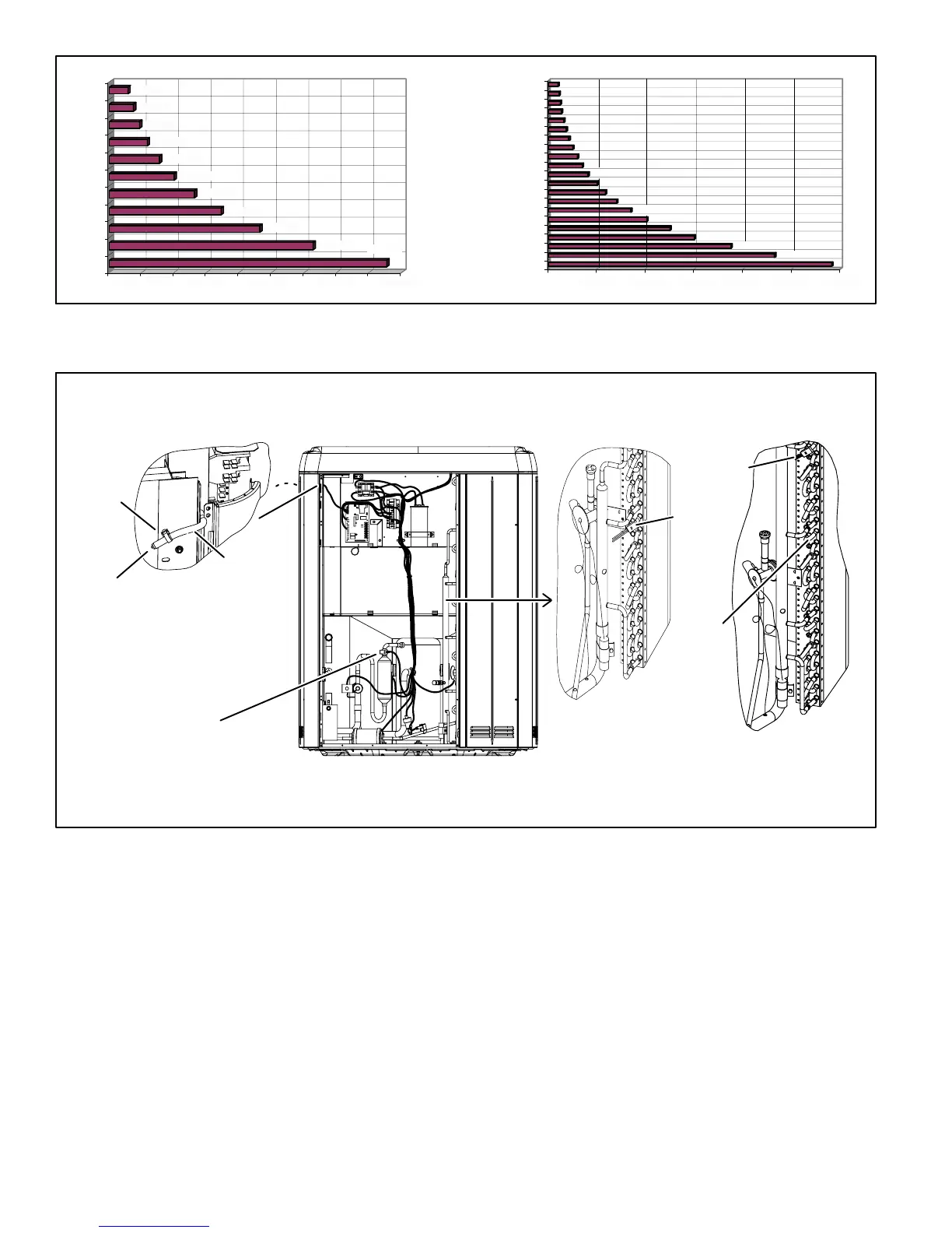
FIGURE 16
FIGURE 17
Sensor Locations
24 tubes up
(after April
2006)
SLEEVE
AMBIENT SENSOR − Extend
tip of plastic sensor just
outside of plastic sleeve.
Place ambient sensor and wire
from defrost board inside of
plastic sleeve and route thru
gap between corner post and
coil support as shown. Secure
with wire tie.
DISCHARGE SENSOR
WIRE TIE
COIL SENSOR −
Clip coil temperature sensor from the defrost board
on the return bend shown on models as follows:
Model −024 & −036: 12 tubes up from bottom (11−1/2");
Model −048 & −060 (before April 2006): 16 tubes up from bottom (15−1/2")
Model −048 & −060 (after April 2006): 24 tubes up from bottom (23−1/2")
Models −024 & −036
Models −048 & −060
16 tubes
up (before
April 2006)
12 tubes up
Ambient SensorThe ambient sensor (shown in detail A,
figure 17) considers outdoor temperatures below −35°F
(−37°C) or above 120°F (48°C) as a problem. If the ambient
sensor is detected as being open, shorted or out of the tem-
perature range of the sensor, the board will not perform de-
mand defrost operation. The board will revert to time/tem-
perature defrost operation and will display the appropriate
fault code. Heating and cooling operation will be allowed in
this fault condition.
Coil SensorThe coil temperature sensor (shown in de-
tail B, figure 17) considers outdoor temperatures below
−35°F (−37°C) or above 120°F (48°C) as a problem. If the
coil temperature sensor is detected as being open, shorted
or out of the temperature range of the sensor, the board will
not perform demand or time/temperature defrost operation
and will display the appropriate fault code. Heating and
cooling operation will be allowed in this fault condition.
Discharge Line SensorIf the discharge line tempera-
ture (shown in figure 17) exceeds a temperature of 285°F
(140°C) during compressor operation, the board will de−en-
ergize the compressor contactor output (and the defrost
output, if active). The compressor will remain off until the
discharge temperature has dropped below 225°F (107°C)
and the 5-minute anti−short cycle delay has been satisfied.
This sensor has two fault and lockout codes:
3−. If the board recognizes five high discharge line temper-
ature faults during a single (Y1) compressor demand,
it reverts to a lockout mode and displays the appropri-
ate code. This code detects shorted sensor or high dis-
charge temperatures. (Code on board is Discharge
Line Temperature Fault and Lockout").

 Loading...


