Page 13
J−Defrost System
The demand defrost controller measures differential tem-
peratures to detect when the system is performing poorly
because of ice build−up on the outdoor coil. The controller
self−calibrates" when the defrost system starts and after
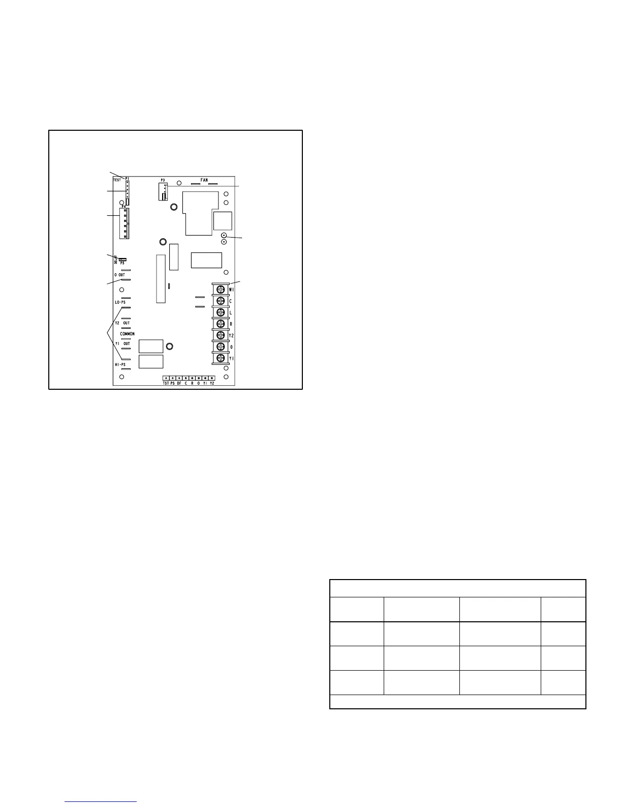
each system defrost cycle. The defrost control board com-
ponents are shown in figure 15.
Defrost Control Board
24V TERMINAL
STRIP
CONNECTIONS
DIAGNOSTIC
LEDS
PRESSURE
SWITCH
CIRCUIT
CONNECTIONS
TEST PINS
Note − Component Locations Vary by Board Manufacturer.
SENSOR PLUG IN
(COIL, AMBIENT,
& DISCHARGE-
SENSORS)
FIGURE 15
REVERSING
VALVE
DELAY
PINS
LOW
AMBIENT
THERMOSTAT
PINS
DEFROST
TERMINATION
PIN SETTINGS
The control monitors ambient temperature, outdoor coil
temperature, and total run time to determine when a de-
frost cycle is required. The coil temperature probe is de-
signed with a spring clip to allow mounting to the outside
coil tubing. The location of the coil sensor is important for
proper defrost operation.
NOTE − The demand defrost board accurately measures
the performance of the system as frost accumulates on the
outdoor coil. This typically will translate into longer running
time between defrost cycles as more frost accumulates on
the outdoor coil before the board initiates defrost cycles.
Diagnostic LEDs
The state (Off, On, Flashing) of two LEDs on the defrost
board (DS1 [Red] and DS2 [Green]) indicate diagnostics
conditions that are described in table 6.
Defrost Board Pressure Switch Connections
The unit’s automatic reset pressure switches (LO PS − S87
and HI PS − S4) are factory−wired into the defrost board on
the LO−PS and HI−PS terminals, respectively.
Low Pressure Switch (LO−PS)When the low pressure
switch trips, the defrost board will cycle off the compressor,
and the strike counter in the board will count one strike. The
low pressure switch is ignored under the following condi-
tions:
during the defrost cycle and 90 seconds after the termina-
tion of defrost
when the average ambient sensor temperature is below
15° F (−9°C)
for 90 seconds following the start up of the compressor
during "test" mode
High Pressure Switch (HI−PS)When the high pressure
switch trips, the defrost board will cycle off the compressor,
and the strike counter in the board will count one strike.
Defrost Board Pressure Switch Settings
High Pressure (auto reset) − trip at 590 psig; reset at 418
psig.
Low Pressure (auto reset) − trip at 25 psig; reset at 40 psig.
5−Strike Lockout Feature
The internal control logic of the board counts the pressure
switch trips only while the Y1 (Input) line is active. If a pres-
sure switch opens and closes four times during a Y1 (In-
put), the control logic will reset the pressure switch trip
counter to zero at the end of the Y1 (Input). If the pressure
switch opens for a fifth time during the current Y1 (Input),
the control will enter a lockout condition.
The 5−strike pressure switch lockout condition can be reset
by cycling OFF the 24−volt power to the control board or by
shorting the TEST pins between 1 and 2 seconds. All timer
functions (run times) will also be reset.
If a pressure switch opens while the Y1 Out line is engaged,
a 5−minute short cycle will occur after the switch closes.
Defrost System Sensors
Sensors connect to the defrost board through a field-re-
placeable harness assembly that plugs into the board.
Through the sensors, the board detects outdoor ambient,
coil, and discharge temperature fault conditions. As the de-
tected temperature changes, the resistance across the
sensor changes. Sensor resistance values can be checked
by ohming across pins shown in table 5. The graph in figure
16 shows sensor temperature to resistance range.
NOTE − When checking the ohms across a sensor, be
aware that a sensor showing a resistance value that is not
within the range shown in table 5, may be performing as de-
signed. However, if a shorted or open circuit is detected,
then the sensor may be faulty and the sensor harness will
need to be replaced.
TABLE 5
Sensor Temperature / Resistance Range
Sensor
Temperature
Range °F (°C)
Resistance values
range (ohms)
Pins/Wire
Color
Outdoor −35 (−37) to 120
(48)
280,000 to 3750 3 & 4
(Black)
Coil −35 (−37) to 120
(48)
280,000 to 3750 5 & 6
(Brown)
Discharge (if
applicable)
24 (−4) to 350
(176)
41,000 to 103 1 & 2
(Yellow)
Note: Sensor resistance increases as sensed temperature decreases.

 Loading...


