Page 16
ActuationWhen the reversing valve is de−energized, the
Y1 circuit is energized, and the coil temperature is below
35°F (2°C), the board logs the compressor run time. If the
board is not calibrated, a defrost cycle will be initiated after
34 minutes of heating mode compressor run time. The con-
trol will attempt to self−calibrate after this (and all other) de-
frost cycle(s).
Calibration success depends on stable system tempera-
tures during the 20−minute calibration period. If the board
fails to calibrate, another defrost cycle will be initiated after
45 minutes (90 minutes for −1 to −4 boards) of heating mode
compressor run time. Once the defrost board is calibrated,
it initiates a demand defrost cycle when the difference be-
tween the clear coil and frosted coil temperatures exceeds
the maximum difference allowed by the control OR after 6
hours of heating mode compressor run time has been
logged since the last defrost cycle.
NOTE − If ambient or coil fault is detected, the board will not
execute the TEST" mode.
TerminationThe defrost cycle ends when the coil tem-
perature exceeds the termination temperature or after 14
minutes of defrost operation. If the defrost is terminated by
the 14−minute timer, another defrost cycle will be initiated
after 34 minutes of run time.
Test ModeWhen Y1 is energized and 24V power is be-
ing applied to the board, a test cycle can be initiated by
placing the termination temperature jumper across the
Test" pins for 2 to 5 seconds. If the jumper remains across
the Test" pins longer than 5 seconds, the control will ignore
the test pins and revert to normal operation. The jumper will
initiate one cycle per test.
Enter the TEST" mode by placing a shunt (jumper) across
the TEST" pins on the board after power−up. (The TEST"
pins are ignored and the test function is locked out if the
shunt is applied on the TEST" pins before power−up).
Board timings are reduced, the low−pressure switch and
loss of charge detection fault is ignored and the board will
clear any active lockout condition.
Each test pin shorting will result in one test event. For
each TEST" the shunt (jumper) must be removed for at
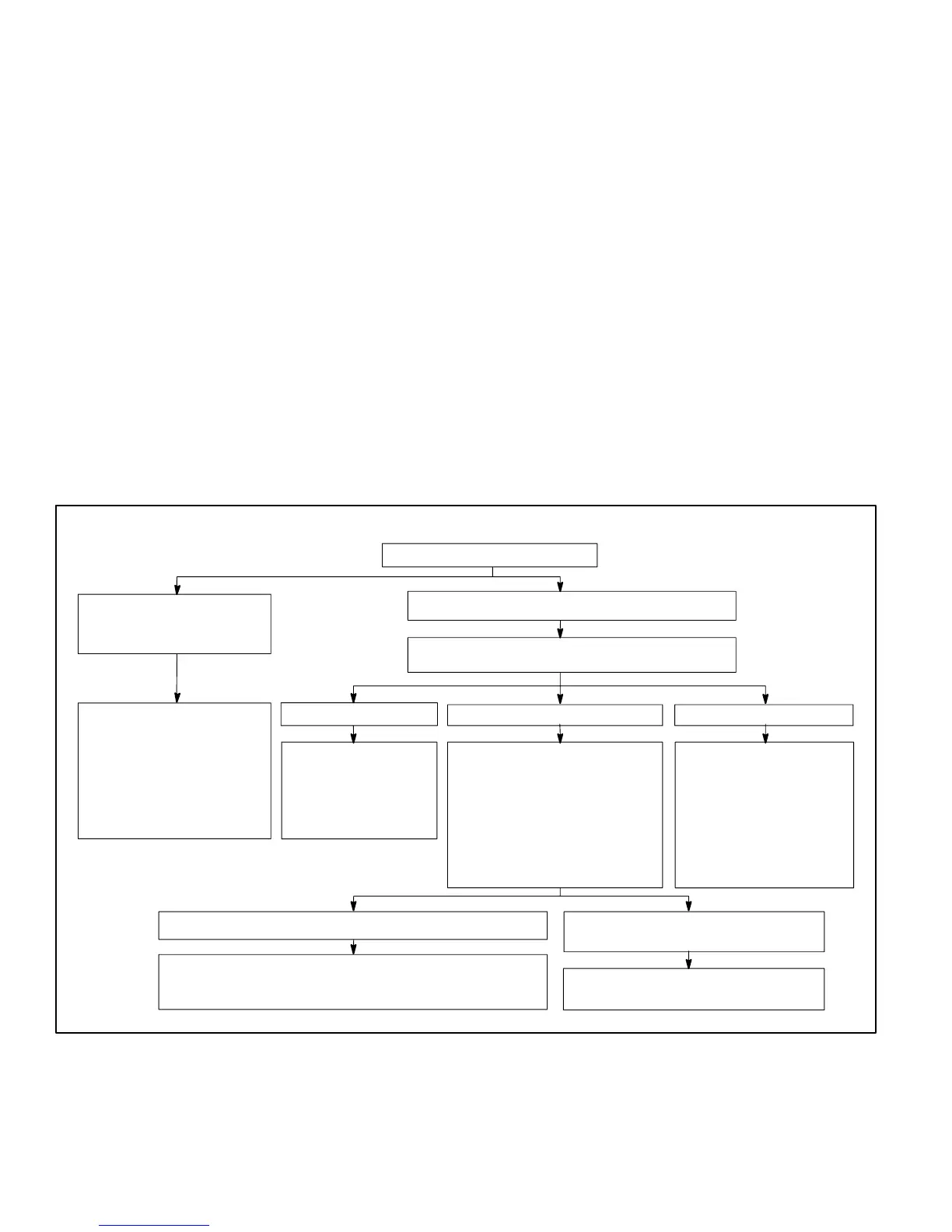
least 1 second and reapplied. Refer to flow chart (figure 18)
for TEST" operation.
Note: The Y1 input must be active (ON) and the O" room
thermostat terminal into board must be inactive.
Defrost Board Diagnostics
See table 6 to determine defrost board operational condi-
tions and to diagnose cause and solution to problems.
If in COOLING Mode If in HEATING Mode If in DEFROST Mode
Short test pins for longer
than 1 second but less than
2.0 seconds
Short test pins for more than 2.0 seconds
Y1 Active (0" line inactive)
FIGURE 18
Test Mode
Test pin short REMAINS in place for more than 5 seconds Test pins short REMOVED before a
maximum of 5 seconds
Clear any short cycle lockout
and 5 strike fault lockout
function, if applicable. No
other functions will be
executed and unit will
continue in the mode it was
operating.
No further test mode
operation will be
executed until the test
short is removed and
reapplied.
The controller will check for
ambient and coil faults (open or
shorted). If a fault exists, the
unit will remain in Heat Mode
and no further test mode
operation will be executed until
the test short is removed and re
applied. If no fault exists, the
unit will go into Defrost mode.
The unit will terminate
defrost and enter Heat
Mode uncalibrated with
defrost timer set for 34
minute test. No further
test mode operation will
be executed until the test
short is removed and
reapplied.
Clear any short cycle lockout and 5 strike
fault lockout function, if applicable.
The unit will return to Heat mode uncalibrated with defrost
timer set for 34 minutes. No further test mode operation will
be executed until the test short is removed and re applied.
The unit will remain in Defrost mode
until termination on time or temperature

 Loading...


