Page 23
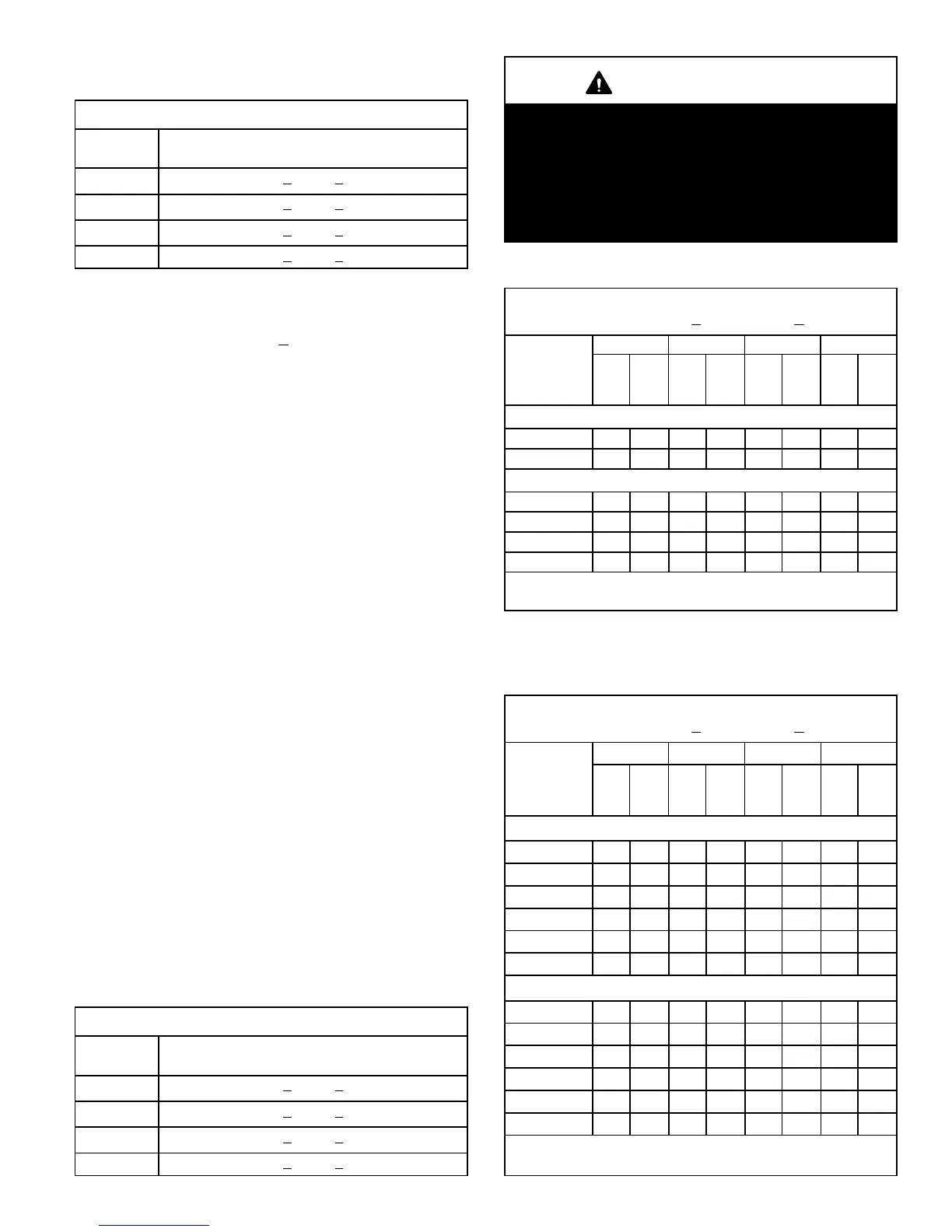
TABLE 10
2nd stage High Capacity
Subcooling Values for Charging
Model
Second-Stage (High Capacity) Subcooling Values
− Conversion Temp. − Liquid Line Temp. °F (°C)
XP19−024 8.0 + 1 (4.4 + .5)
XP19−036 6.0 + 1 (3.3 + .5)
XP19−048 6.0 + 1 (3.3 + .5)
XP19−060 6.0 + 1 (3.3 + .5)
Charging Using Normal Operating Pressures
and the Approach Method
Outdoor Temp. >
65F (18C)
The following procedure is intended as a general guide and
is for use on expansion valve systems only. For best results,
indoor temperature should be 70°F (21°C) to 80°F (26°C).
Monitor system pressures while charging.
1 − Record outdoor ambient temperature using a digital
thermometer.
2 − Attach high pressure gauge set and operate unit for
several minutes to allow system pressures to stabilize.
3 − Compare stabilized pressures with those provided in
tables 12 and 13, Normal Operating Pressures." Mi-
nor variations in these pressures may be expected due
to differences in installations. Significant differences
could mean that the system is not properly charged or
that a problem exists with some component in the sys-
tem. Pressures higher than those listed indicate that
the system is overcharged. Pressures lower than
those listed indicate that the system is undercharged.
Verify adjusted charge using the approach method.
Approach Method
4 − Use the same digital thermometer used to check out-
door ambient temperature to check liquid line tempera-
ture. Verify the unit charge using the approach method.
5 − The difference between the ambient and liquid temper-
atures should match values given in table 11. If the val-
ues don’t agree with the those in table 11, add refriger-
ant to lower the approach temperature or recover re-
frigerant from the system to increase the approach
temperature.
TABLE 11
2nd Stage High Capacity
Approach Values for Charging
Model
Second-Stage (High Capacity) Approach Temp. −
Liquid Line Temp. − Outdoor Ambient °F (°C)
XP19−024 7.0 + 1 (3.9 + .5)
XP19−036 9.0 + 1 (5.0 + .5)
XP19−048 7.0 + 1 (3.9 + .5)
XP19−060 9.0 + 1 (5.0 + .5)
IMPORTANT
Use table 12 and table 13 as a general guide when
performing maintenance checks. This is not a proce-
dure for charging the unit (Refer to Charging/Check-
ing Charge section). Minor variations in these pres-
sures may be expected due to differences in installa-
tions. Significant differences could mean that the
system is not properly charged or that a problem ex-
ists with some component in the system.
TABLE 12
Normal Operating Pressure (Heating
Operation) − Liquid +
10 & Vapor +5 PSIG*
Entering Air
Temperature
5F (5C)
LIQ-
UID
VA-
PO
R
LIQ-
UID
VA-
PO
R
LIQ-
UID
VA-
PO
R
LIQ-
UID
VA-
PO
R
First Stage (Low Capacity)
40 (4.4) 302 99 301 95 324 93 342 90
50 (10) 318 121 317 114 351 117 388 112
Second Stage (High Capacity)
20 (−7.0) 280 67 280 57 337 74 346 60
30 (−1.0) 297 82 298 75 342 76 365 71
40 (4.4) 317 99 313 89 352 89 390 84
50 (10) 330 118 328 87 379 107 402 104
*These are typical pressures only. Indoor match up, indoor air
quality, and indoor load will cause the pressures to vary.
TABLE 13
Normal Operating Pressure (Cooling
Operation) − Liquid +
10 & Vapor +5 PSIG*
Entering Air
Temperature
5F (5C)
LIQ-
UID
VA-
PO
R
LIQ-
UID
VA-
PO
R
LIQ-
UID
VA-
PO
R
LIQ-
UID
VA-
PO
R
First Stage (Low Capacity)
65 (18.3) 226 152 230 148 210 136 234 135
75 (23.9) 262 151 267 150 242 138 274 137
85 (29.4) 304 152 309 153 286 140 314 142
95 (35.0) 351 155 355 155 328 142 361 147
105 (40.6) 400 158 404 157 374 144 413 147
115 (49.0) 454 161 460 159 426 146 470 149
Second Stage (High Capacity)
65 (18.3) 228 146 236 144 227 114 237 131
75 (23.9) 267 148 275 145 265 123 276 133
85 (29.4) 309 149 318 148 306 132 320 135
95 (35.0) 358 151 365 150 348 138 369 138
105 (40.6) 410 152 416 153 397 141 423 140
115 (49.0) 465 154 473 155 453 143 482 144
*These are typical pressures only. Indoor match up, indoor air
quality, and indoor load will cause the pressures to vary.

 Loading...


