Page 17
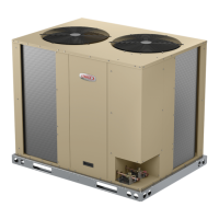
ELS-120,150-G,J,M,Y
537904-01
K66,-1,2
K67,-1,2
DENOTES OPTIONAL COMPONENTS
LINE VOLTAGE FIELD INSTALLED
C
4
R
TB14
TB14
K10,-1
TB14
TERMINAL STRIP-CLASS II VOLTAGE
CB8
CIRCUIT BREAKER-TRANS T1
S24
S25
T1
SWITCH-LOSS OF CHARGE,COMP 1
SWITCH-LOSS OF CHARGE,COMP 2
TRANSFORMER-CONTROL
SECTION A 3
WIRING DIAGRAM
4
S25
S24
3
1
CB8
T1
208V
COOL 1
COOL 2
C2
C1
208V
2
2
1
3
1
3
B4
B5
K2-2
6
2008
08/17
400V
240 / 460 / 575V
400V
240 / 460 / 575V
K1-2
REV. 0
II
FIGURE 8. Typical Wiring Diagram – ELS120S4D and ELS150S4D (G, J, M, Y Voltages)
 Loading...