Page 1
WARNING
Improper installation, adjustment, alteration, service
or maintenance can cause property damage, personal
injury or loss of life. Installation and service must be
performed by a licensed professional HVAC installer or
equivalent, service agency, or the gas supplier.
IMPORTANT
The Clean Air Act of 1990 bans the intentional venting of
refrigerant (CFCs, HCFCs and HFCs) as of July 1, 1992.
Approved methods of recovery, recycling or reclaiming
must be followed. Fines and/or incarceration may be
levied for noncompliance.
WARNING
Electric shock hazard! - Disconnect all power
supplies before servicing.
Replace all parts and panels before
operating.
Failure to do so can result in death or
electrical shock.
CAUTION
As with any mechanical equipment, contact with sharp
sheet metal edges can result in personal injury. Take
care while handling this equipment and wear gloves and
protective clothing.
Table of Contents
Unit Plumbing Parts Arrangement .................................5
Model Number Identication ........................................10
Unit Control Box Components Arrangement ................ 11
I-UNIT COMPONENTS ................................................12
A-CONTROL BOX COMPONENTS ............................12
B-COOLING COMPONENTS .......................................12
II- REFRIGERANT SYSTEM ....................................... 13
A-Plumbing ..................................................................13
B-Service Valves .........................................................14
III-START-UP ................................................................15
IV-CHARGING ..............................................................16
A-Leak Testing .............................................................. 16
B-Evacuating the System .............................................17
C-Charging ...................................................................18
V-MAINTENANCE ........................................................ 22
VI-Wiring Diagram and Sequence of Operation ...........23
ELS
6 - 20 TON
Service Literature
UNIT INFORMATION
Corp. 1811-L3
May 15, 2018
ELS SERIES UNITS
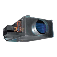
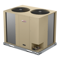
The ELS units are designed for light commercial applica-
tions, with a remotely located blower-coil unit or a furnace
with an add-on evaporator coil. Capacities for the series
are 6, 7-1/2, 10, 12.5, 15 and 20 tons (21, 26, 35, 44,
53, and 70 kW).ELS072, ELS090 and ELS120S4S mod-
els have one dual-speed scroll compressor. ELS120S4D,
ELS150S4D, ELS180S4D and ELS240S4D models have
two single-speed scroll compressors. ELS units match
with the ELA blower-coil units. All ELS units are three
phase and use HFC-410A refrigerant.
This manual covers ELS072S4S, ELS090S4S,
ELS120S4S, ELS120S4D, ELS150S4D, ELS180S4D and
ELS240S4D units. It is divided into sections which discuss
the major components, refrigerant system, charging pro-
cedure, maintenance and operation sequence.
Information in this manual is intended for qualied service
technicians only. All specications are subject to change.
Procedures in this manual are presented as a recommen-
dation only and do not supersede or replace local or state
codes.