Page 17
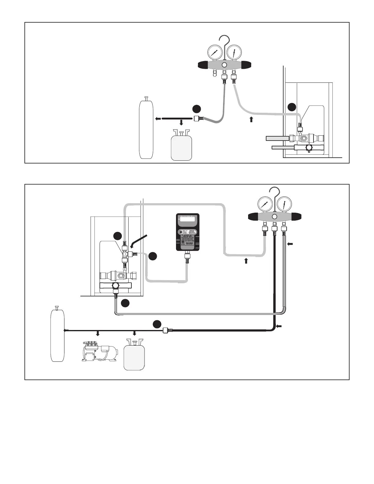
TO SUCTION
SERVICE VALVE
HFC-410A
GAUGE SET
NITROGEN
OUTDOOR UNIT
Connect an HFC-410A manifold gauge set high pressure hose to the
suction valve service port.
B With both manifold valves closed, connect the cylinder of HFC-410A
refrigerant to the center port of the manifold gauge set.
C After the line set has been connected to both the indoor and outdoor
units, check the line set connections and indoor unit for leaks. Use the
following procedure to test for leaks:
A
B
NOTE - LATER IN THE PROCEDURE, THE HFC-410A CONTAINER WILL BE REPLACE BY THE
NITROGEN CONTAINER.
FIGURE 6
B-Evacuating the System
OUTDOOR UNIT
TO SUCTION
SERVICE VALVE
TO LIQUID
LINE SERVICE
VALVE
MICRON GAUGE
VACUUM PUMP
A34000 1/4 SAE
TEE WITH
SWIVEL
COUPLER
NITROGEN
50
MANIFOLD
GAUGE SET
HFC-410A
RECOMMEND MINIMUM
3/8” HOSE
A Connect low side of manifold gauge set with 1/4 SAE in-line tee to suction line
service valve
B Connect high side of manifold gauge set to liquid line service valve
C Connect micron gauge available connector on the 1/4 SAE in-line tee.
D Connect the vacuum pump (with vacuum gauge) to the center port of the
manifold gauge set. The center port line will be used later for both the
HFC-410A and nitrogen containers.
A
B
C
D
NOTE - Remove cores from service valves if not already done.
FIGURE 7
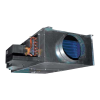
 Loading...
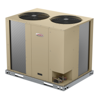