EasyManua.ls Logo

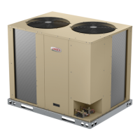
Lennox Enlight LGT Series

Lennox Enlight LGT Series
106 pages
To Next Page IconTo Next Page
Loading...
Page 1
UNIT INFORMATIONUNIT INFORMATION
Service Literature
WARNING
To prevent serious injury or death:
1- Lock-out/tag-out before performing maintenance.
2- If system power is required (e.g., smoke detector
maintenance), disable power to blower, remove
fan belt where applicable, and ensure all
controllers and thermostats are set to the “OFF”
position before performing maintenance.
3- Always keep hands, hair, clothing, jewelry, tools,
etc., away from moving parts.
WARNING
Improper installation, adjustment, alteration,
service or maintenance can cause property damage,
personal injury or loss of life. Installation and service
must be performed by a licensed professional HVAC
installer or equivalent, service agency, or the gas
supplier
Table of Contents
Options / Accessories . . . . . . . . . . . . . . . . . . . . . Page 2




Unit Parts Arrangement . . . . . . . . . . . . . . . . . . . Page 18
I-Unit Components . . . . . . . . . . . . . . . . . . . . . . . Page 18












options.

      



-


       
-



-


-

stages.
󰀨-

-
       


       
       

   󰀩

      

    


   -





LGT SERIES
13 to 25 ton
45.7 to 88 kW


LGT156 through 300
Question and Answer IconNeed help?

Do you have a question about the Lennox Enlight LGT Series and is the answer not in the manual?

Lennox Enlight LGT Series Specifications

General IconGeneral
BrandLennox
ModelEnlight LGT Series
CategoryFan
LanguageEnglish

Summary

UNIT INFORMATION

Service Literature

OPTIONS ACCESSORIES

COOLING SYSTEM

Lists available options and accessories for the cooling system.

HEATING SYSTEM

Details optional accessories for the heating system configurations.

BLOWER - SUPPLY AIR

Lists various blower options and related accessories.

SPECIFICATIONS

General Data

Provides basic unit information like model, tonnage, and efficiency type.

Cooling Performance

Details cooling capacity, airflow, power consumption, and efficiency ratings.

Gas Heating Performance

Outlines gas heating input, output, temperature rise, and efficiency.

BLOWER DATA

FACTORY INSTALLED BELT DRIVE KIT SPECIFICATIONS

Details specifications for factory-installed belt drive kits including HP and RPM.

CEILING DIFFUSER AIR RESISTANCE

Lists static pressure resistance for different ceiling diffuser types.

ELECTRICAL DATA

Compressor Data

Shows rated and locked rotor amps for compressors across different voltages.

Indoor Blower Motor

Lists horsepower and full load amps for the indoor blower motor.

I-UNIT COMPONENTS

Control Box Components

Describes components found within the unit's control box.

Burner Controls A3 & A12

Explains the function of burner controls A3 and A12 for gas heat sections.

Component Details

High Pressure Switches

Describes the function and operation of high pressure switches.

Temperature Thermistors

Details the location and function of temperature thermistors for system monitoring.

Blower Adjustment Procedures

Determining Unit CFM

Outlines the process for measuring and setting the unit's cubic feet per minute (CFM).

Blower Belt Adjustment

Provides instructions for proper blower belt alignment and tension maintenance.

Gas Heat Components

Burner Ignition Control

Describes the functions of the ignition control for gas heating, including LED codes.

Heat Exchanger

Explains how to access and remove the heat exchanger for service or replacement.

III-CHARGING

Refrigerant Charge and Check

Provides procedures for checking and adjusting refrigerant charge for optimal performance.

Charge Confirmation and Fine Tuning

Details methods for confirming and fine-tuning refrigerant charge using liquid temperature.

IV- START-UP OPERATION

Preliminary and Seasonal Checks

Outlines essential pre-operation checks for safety and functionality.

Cooling Start-up

Describes the steps for initiating and verifying proper cooling operation.

Heating Startup

V- SYSTEMS SERVICE CHECKS

Heating System Service Checks

Covers checks for gas piping, supply pressure, and manifold pressure.

Flame Sensing

Details the procedure for measuring flame current and ensuring proper sensing.

VI-MAINTENANCE

Filters

Instructs on checking, cleaning, or replacing air filters regularly for optimal performance.

Condenser Coil

Details the procedure for cleaning the condenser coil annually and inspecting connecting lines.

VII-ACCESSORIES

Roof Curbs

Describes the application and installation of various roof curbs for unit mounting.

Economizer

Details the operation and modes of the optional economizer system.

VIII-FACTORY-INSTALLED Hot Gas Re-Heat

General

Explains the function of hot gas reheat for dehumidification mode.

Check-Out

Provides a procedure for testing the hot gas reheat operation.

IX-Multi-Staged Blower

Set Blower Speeds

Details using the mobile app to enter and set blower speeds based on design specifications.

X-VAV System

Start-Up

Outlines the start-up procedure for VAV systems, including transducer installation.

Manual Supply Air VFD Bypass

Provides instructions for manually bypassing the VFD for constant air volume operation.

XI-Wiring Diagrams and Sequence of Operation

Gas Heat Diagram

Presents the electrical wiring diagram for the gas heat section of the unit.

Sequence of Operation Gas Heat LGT156300

First Stage Heat

Describes the sequence of events for the first stage of gas heating operation.

Second Stage Heat

Details the sequence of operation for the second stage of gas heating.

Sequence of Operation LGT156

First Stage Cooling

Details the sequence for initiating and operating the first stage of cooling.

Second Stage Cooling

Describes the sequence for engaging the second stage of cooling.

Blower Operation

Outlines blower operation modes, both with and without bypass.

Related product manuals