Page 22
16-Second-Stage Power Exhaust Relay K231
(Staged-Blower units equipped with power exhaust)
-
-
17-Outdoor Fan Transformers T5
18-Fuse F61 (Higher SCCR units only)
19-Blower Motor Overload Relay S42
-
CLEAR
COVER
(SHOWN
CLOSED)
STOP
BUTTON
(RED)
RED TEST
BUTTON
(Push To Test)
AMP SETTING
CONTROL
(BLUE DIAL)
TRIP
INDICATION
WINDOW
LINE VOLTAGE IN
AMP SETTING
POINTER
BLUE RESET SCREW
(Shown in AUTO position as
shipped from the factory)
LOAD VOLTAGE
OUT
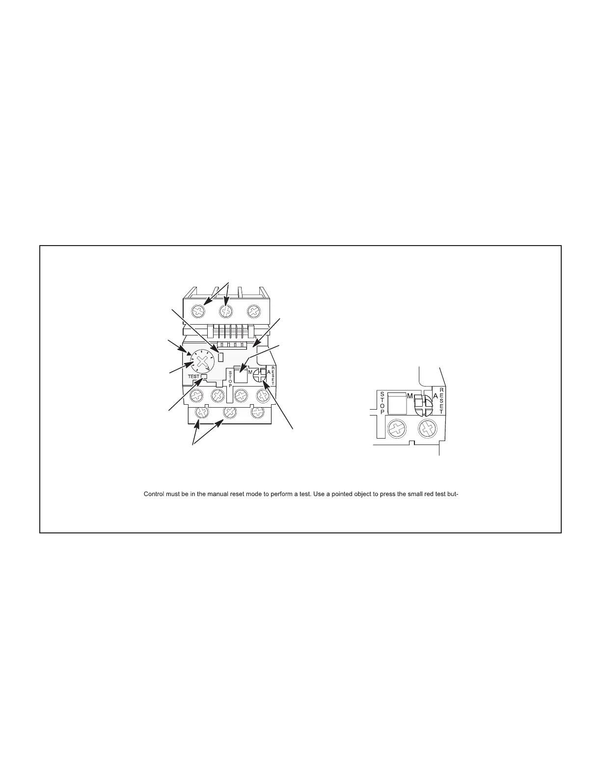
DETAIL SHOWING RESET BUTTON
ADJUSTED TO MANUAL POSITION
Lift clear cover and turn adjustment screw
counterclockwise. Reset screw will pop out
when pointer is in M (manual position). Close
cover to lock reset screw into position.
TELEMECANIQUE OVERLOAD RELAY
Lift clear cover to adjust relay amp setting according to value given on the blower motor nameplate. Proper relay
amp setting equals motor nameplate FLA X service factor of 1.15 X .95.
Cover must also be lifted to adjust control mode from automatic reset to manual reset (see detail above) and to
test the control.
ton. A yellow marker should appear in the trip indication window to the right of the amp setting control. Press the
blue reset screw to reset the relay.
The red STOP button opens the normally closed contacts which power the blower motor. This button stops blower
motor operation as long as it is pressed in.
FIGURE 5
 Loading...