๎ณ๎๎๎๎๎๎
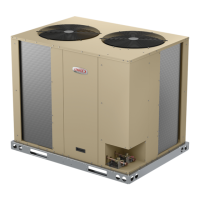
3-Burner Assembly (Figure 23)
๎ท๎๎๎๎
๎๎๎๎๎๎๎๎๎๎๎๎๎๎๎๎๎๎๎๎๎๎๎
๎๎๎๎๎๎๎๎๎๎๎๎๎๎๎๎๎๎๎๎๎๎๎๎๎๎๎๎
๎๎๎๎๎๎๎๎๎๎๎๎๎๎๎๎๎๎๎๎๎๎๎๎๎๎๎๎๎๎๎๎๎๎๎๎๎
๎๎๎๎๎๎๎๎๎๎๎๎
๎๎๎๎๎๎๎
๎ท๎๎๎ ๎๎๎๎๎๎ ๎๎๎๎๎๎๎๎๎๎๎ ๎๎๎๎๎ ๎๎๎๎๎๎๎๎ ๎๎๎๎๎๎๎๎๎๎ ๎๎๎๎ ๎๎๎๎
๎๎๎๎๎๎ ๎๎๎๎ ๎๎๎๎๎๎๎๎๎ ๎๎๎๎๎๎๎๎๎๎๎ ๎
๎๎ ๎๎๎๎๎๎๎๎๎ ๎๎๎๎๎๎๎๎๎ ๎ฌ๎๎๎๎๎๎๎๎
๎๎๎๎๎๎๎๎ ๎๎๎๎ ๎๎๎๎
๎๎๎๎๎๎๎ ๎๎๎๎ ๎
๎๎๎๎๎๎ ๎๎๎ ๎๎๎๎๎๎๎๎๎๎๎ ๎
๎๎ ๎ธ๎๎๎๎
๎ฆ๎๎๎๎๎๎๎๎๎๎๎ค๎๎๎
Burners
๎ค๎๎๎๎๎๎๎๎๎๎๎๎๎๎๎๎๎๎๎๎๎๎๎๎๎๎๎๎๎
๎๎๎๎๎๎๎๎๎๎ฅ๎๎๎๎๎๎๎ ๎๎๎๎ ๎๎๎๎๎๎๎๎
๎๎๎๎๎๎๎๎๎๎๎๎๎๎๎๎๎๎๎๎๎๎๎๎๎๎๎๎๎๎๎๎๎๎๎๎ค๎๎๎๎๎๎๎๎๎๎๎๎๎๎๎๎๎๎๎๎๎๎
๎๎๎๎๎๎๎๎๎๎๎๎๎๎๎๎๎๎๎๎๎๎๎๎๎๎๎๎๎๎๎๎๎๎๎๎๎๎๎๎๎๎๎๎๎๎๎๎๎๎๎๎๎๎๎๎๎๎๎
๎ค๎๎๎๎๎๎ ๎๎๎๎๎๎๎๎ ๎๎๎๎ ๎๎๎๎๎ ๎๎๎๎๎ ๎๎๎๎ ๎๎๎๎๎๎๎ ๎๎๎๎๎๎ ๎๎๎ ๎๎๎๎๎๎๎
๎ฅ๎๎๎๎๎๎๎๎๎๎๎๎
๎๎๎๎๎๎๎๎๎๎๎๎๎๎๎๎๎๎๎๎๎๎๎๎ฅ๎๎๎๎๎๎๎๎๎๎๎๎๎๎๎๎๎๎
๎๎๎๎๎๎๎๎๎๎๎๎๎๎๎๎๎๎๎๎๎๎๎๎๎๎๎๎๎๎๎๎ถ๎จ๎ต๎น๎ฌ๎ฆ๎จ๎๎ฆ๎ซ๎จ๎ฆ๎ฎ๎ถ๎๎๎๎๎๎๎๎๎
๎๎๎๎๎๎๎๎๎๎๎๎๎๎๎
TYPICAL GAS BURNER ASSEMBLY
FIGURE 23
๎ฒ๎๎๎ฟ๎๎
๎จ๎๎๎๎๎
๎๎๎๎๎๎๎๎๎๎๎๎๎๎๎๎๎๎ฟ๎๎๎๎๎ฟ๎๎๎๎๎๎๎๎๎๎๎๎๎๎๎๎๎๎๎๎๎๎๎๎๎๎๎๎
๎๎๎๎๎๎๎๎๎๎๎๎๎๎๎๎
๎๎๎๎๎๎๎๎๎๎๎๎๎๎ฌ๎๎๎๎๎๎๎๎๎๎๎๎๎๎๎๎๎๎๎๎ฟ๎๎๎๎๎๎๎๎๎
๎๎๎๎๎๎๎๎๎๎๎๎๎๎๎๎๎๎๎ท๎๎๎๎๎๎๎ฟ๎๎๎๎๎๎๎๎๎๎๎๎๎๎๎๎๎๎๎๎๎๎๎๎๎
๎๎๎๎๎๎
๎๎๎๎๎๎๎๎๎๎๎ท๎๎๎๎
๎๎๎๎๎๎๎๎๎๎๎๎๎๎๎๎๎๎๎๎
๎๎ ๎๎๎๎ ๎๎๎๎ฟ๎๎๎๎๎๎๎๎๎๎๎๎
๎๎๎๎๎๎๎๎๎๎๎๎๎๎๓ฐจ๎๎๎๎๎๎๎๎๎๎๎๎๎
NOTE-Do not use thread sealing compound on the ori๎ฟc-
es. Using thread sealing compound may plug the ori๎ฟces.
Natural gas ori๎ฟce size is on nameplate. The LP gas ori-
๎ฟce size is on the label provided in the LP kit.
NOTE- In primary and secondary high temperature limits
S10 and S99 the ignition circuits in both gas heat sections
one and two are immediately de-energized when termi-
nals 1-3 open and the indoor blower motor is immediately
energized when terminals 1-2 close. This is the primary
and secondary safety shut-down function of the unit.
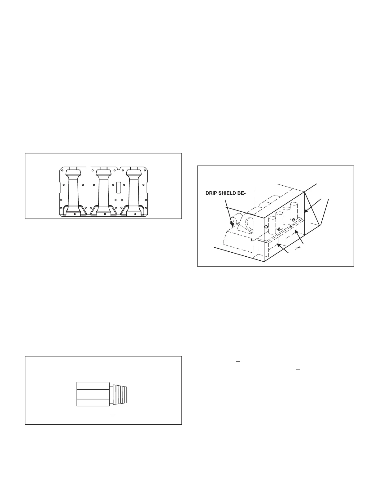
PIPE THREADS
Tighten to 6.25 + .5 ft.lbs.
Do not over-tighten.
FIGURE 24
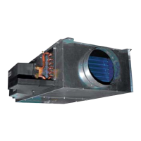
4-Primary High Temperature Limits S10 & S99
๎ถ๎๎๎๎๎๎๎๎๎๎๎๎๎๎๎๎๎๎๎๎๎๎๎๎๎๎๎๎๎๎๎๎๎๎๎๎๎๎๎๎๎๎๎๎๎๎๎๎๎๎๎๎๎๎๎๎๎-
๎๎๎๎๎๎๎๎๎๎๎๎๎๎ถ๎๎๎๎๎๎๎๎๎๎๎๎๎๎๎๎๎๎๎๎๎๎๎๎๎๎๎๎๎๎๎๎๎๎๎๎๎๎๎๎๎๎๎๎๎
๎๎๎๎๎๎๎๎๎๎๎๎๎๎๎๎๎๎๎๎๎
๎ฌ๎๎๎ฏ๎ช๎ท๎๎๎๎๎๎๎๎๎๎๎๎๎๎๎๎ถ๎๎๎๎๎๎๎๎ถ๎๎๎๎๎๎๎๎๎๎๎๎๎๎๎๎๎๎๎๎๎๎๎๎๎๎๎
๎๎๎๎๎๎๎๎
๎๎๎๎๎๎๎๎๎๎๎
๎๎๎๎๎๎๎๎๎๎๎๎๎๎๎๎ฌ๎๎๎๎๎๎๎๎๎๎๎๎๎๎๎๎๎ถ๎๎๎๎๎๎๎
๎ถ๎๎๎๎๎๎๎๎๎๎๎๎๎๎๎๎๎๎๎๎๎๎๎๎๎๎๎๎๎๎๎๎๎๎๎๎ถ๎๎๎๎ฟ๎๎๎๎๎๎๎๎
๎ณ๎๎๎๎๎๎๎๎๎๎๎๎๎๎ถ๎๎๎๎๎๎๎๎๎๎๎๎๎๎๎๎๎๎๎๎ธ๎๎๎๎๎ฆ๎๎๎๎๎๎๎๎๎๎๎ค๎๎๎๎๎๎๎๎๎
๎๎๎๎๎๎๎๎๎๎๎
๎๎๎๎๎๎๎๎๎๎๎๎๎๎๎๎๎๎ค๎๎๎๎๎๎๎๎๎๎๎๎๎๎๎๎๎๎๎๎๎๎๎๎๎ถ๎๎๎๎๎๎
๎๎๎๎๎๎๎๎๎๎๎๎๎๎ค๎๎๎๎ธ๎๎๎๎๎ฆ๎๎๎๎๎๎๎๎๎๎๎๎๎๎๎๎๎๎๎๎๎๎๎๎๎๎๎
๎๎๎๎๎๎๎๎
๎๎๎๎๎๎๎๎ ๎๎ค๎๎๎๎๎ ๎ฌ๎๎๎ ๎ฑ๎๎ฆ๎๎ ๎๎๎๎๎๎๎๎๎ ๎๎๎๎๎ ๎๎๎ ๎๎๎๎๎๎๎๎๎๎๎๎ ๎๎๎๎
๎๎๎๎๎๎๎๎๎๎๎๎๎๎๎๎๎๎๎๎๎๎๎๎๎๎๎๎๎๎๎๎๎๎๎๎๎๎๎๎๎๎๎๎๎๎๎๎๎๎๎๎๎๎๎๎๎๎
๎๎๎๎๎
๎๎๎๎๎๎๎๎๎๎๎๎๎๎๎๎๎๎๎๎ค๎๎๎๎๎๎๎๎๎๎๎๎๎๎๎๎๎๎๎๎๎๎ฑ๎๎ฒ๎๎๎๎๎-
๎๎๎๎๎๎๎๎๎๎ถ๎๎๎๎๎๎๎๎ถ๎๎๎๎๎๎๎๎๎๎๎๎๎๎๎๎๎๎๎๎๎๎๎๎๎
๎๎๎๎๎๎๎๎๎๎๎๎๎๎๎๎๎
๎ฎ๎๎๎๎๎๎๎๎๎๎๎๎๎๎๎๎๎๎๎ค๎๎๎๎๎ฌ๎๎๎๎๎๎๎๎๎๎๎๎๎๎๎๎๎๎๎๎๎๎๎๎๎๎
๎๎๎๎๎๎๎๎๎๎๎
๎
๎๎๎๎๎๎๎๎๎๎๎๎๎๎ฏ๎๎๎๎๎๎ ๎๎๎๎๎๎๎๎๎ ๎๎๎๎ ๎๎๎๎๎๎๎๎ ๎๎๎๎๎๎๎๎๎๎๎๎๎๎๎
๎
๎๎๎๎๎๎๎๎๎๎๎๎๎ฌ๎๎๎๎๎๎๎๎๎๎๎๎๎๎
๎๎๎๎๎๎๎๎๎๎๎๎๎๎๎๎๎๎๎๎๎๎๎๎๎๎๎๎๎
๎๎๎๎๎๎๎๎๎๎๎๎
๎๎๎๎๎๎๎๎๎ถ๎๎๎๎ต๎๎๎๎๎๎๎ณ๎๎๎๎๎๎ซ๎๎๎๎
๎๎๎๎
S10 and S99 Location
CONDENSER
DIVIDER
PANEL
S10 AND S99 ON
HIND BLOWER
HOUSING
GAS HEAT
SECTION 1
GAS HEAT
SECTION 2
FIGURE 25
5-Flame Rollout Limits S47, S69
๎ฉ๎๎๎๎๎๎๎๎๎๎๎๎๎๎๎๎๎๎๎๎๎ถ๎๎๎๎๎๎๎ฟ๎๎๎๎๎๎๎๎๎๎๎๎๎๎๎๎๎๎๎๎๎๎ถ๎๎๎๎๎๎
๎๎๎๎๎๎๎ ๎๎๎๎๎ ๎๎๎๎๎๎๎๎ ๎๎๎๎ ๎ถ๎ณ๎ถ๎ท๎ ๎ฑ๎๎ฆ๎๎ ๎๎๎๎๎ ๎๎๎๎๎๎๎๎๎๎๎๎
๎๎๎๎๎๎๎๎๎๎๎๎๎๎๎๎๎๎๎๎๎๎
๎๎๎๎๎๎๎๎๎
๎๎๎๎๎๎๎๎๎๎๎๎๎๎๎๎๎๎๎๎๎๎๎๎๎๎๎๎
๎๎๎๎ ๎
๎๎๎๎๎๎ ๎๎๎๎๎๎๎๎๎๎๎๎๎๎๎๎ ๎ฟ๎๎๎๎๎๎๎๎๎ ๎ฅ๎๎๎๎ ๎๎๎๎๎๎๎๎๎ ๎๎๎๎
๎๎๎๎๎๎๎๎๎๎๎๎๎๎ค๎๎๎๎ธ๎๎๎๎๎ฆ๎๎๎๎๎๎๎๎๎๎๎๎บ๎๎๎๎๎ถ๎๎๎๎๎๎๎ถ๎๎๎๎๎๎๎๎๎๎
๎๎๎๎๎๎๎๎๎๎๎๎๎๎๎๎๎๎๎๎๎๎๎๎๎๎๎๎
๎๎๎๎๎๎๎๎๎๎๎๎๎๎๎๎๎๎๎
๎๎๎๎๎๎๎๎๎๎๎
๎๎๎๎๎๎๎๎๎๎๎๎๎๎๎๎๎๎๎๎๎๎๎๎๎๎๎๎๎๎๎๎๎๎๎๎๎๎๎๎๎๎๎๎๎๎๎๎๎๎๎๎๎๎๎๎๎๎
๎๎๎๎๎๎๎๎๎๎๎๎๎๎๎๎๎๎๎๎๎๎๎๎๎๎๎๎๎๎๎๎๎๎๎๎๎๎๎๎๎๎๎๎๎๎๎๎๎๎๎๎๎๎๎๎ฏ๎๎๎๎๎
๎ถ๎๎๎๎๎๎๎๎ถ๎๎๎๎๎๎๎๎๎๎๎๎๎๎๎๎๎๎๎๎๎๎๎๎๎๎๎๎๎๎๎๎๎๎๎๎๎๎๎๎๎๎๎๎๎๎๎๎
๎๎๎๎๎๎๎๎๎๎๎๎๎ฉ๎+๎๎๎๎๎ฉ๎๎๎๎๎๎๎๎๎๎๎๎๎๎๎๎๎๎๎๎๎๎๎๎๎๎๎๎๎๎๎๎๎๎๎๎๎๎
๎๎๎๎๎๎๎๎๎๎๎๎
๎๎๎๎๎๎๎๎๎๎๎๎๎๎๎๎๎๎๎๎๎๎๎๎ฉ๎+ 12 F on a tempera-
๎๎๎๎๎๎๎๎๎๎๎๎ค๎๎๎๎๎๎๎๎๎๎๎๎๎๎๎๎๎๎๎๎๎๎๎๎๎๎๎๎๎๎๎๎๎๎๎๎๎๎๎๎
6-Combustion Air Prove Switches S18, S45
๎ณ๎๎๎๎๎๎๎๎๎๎๎๎๎๎๎ถ๎๎๎๎๎ฟ๎๎๎๎๎๎๎๎๎๎๎๎๎๎๎๎๎๎๎๎๎๎๎ถ๎๎๎๎๎๎๎๎๎๎๎
๎๎๎๎๎๎๎๎๎๎๎๎๎๎๎๎๎๎๎๎๎๎๎๎๎๎๎๎๎๎๎๎๎๎๎๎๎๎๎๎๎๎๎๎๎๎๎๎๎๎๎๎๎๎๎๎๎
๎จ๎๎๎๎ ๎๎๎๎ ๎๎๎๎ ๎๎๎๎ ๎๎๎๎๎๎๎๎ ๎
๎๎๎๎ ๎ฅ๎๎๎๎ ๎๎๎๎ ๎๎๎๎๎๎๎๎๎๎ ๎ถ๎ณ๎ถ๎ท๎
๎ฑ๎๎ฒ๎๎๎๎๎๎๎๎๎๎๎๎๎๎๎๎๎๎๎๎๎๎๎๎๎๎๎
๎๎๎๎๎๎๎ ๎๎๎๎ ๎๎๎๎๎๎๎๎ ๎๎๎๎-
๎๎๎๎๎๎๎๎ถ๎๎๎๎๎๎๎ถ๎๎๎๎๎๎๎๎ถ๎๎๎๎๎๎๎๎๎๎๎๎๎๎๎๎๎๎๎๎๎ค๎๎๎๎ธ๎๎๎๎๎ฆ๎๎-
๎๎๎๎๎๎๎๎