THERMOSTATS
FIGURE 3
TYPICAL FUSEIDISCONNECT
SWITCH BOX MOUNTED ON FURNACE
FOR UNIT TO
OPERATE DISCONNECT
SWITCH MUST
BF IN "Off' POSITION
FIGURE 4
GAS VALVE LOCATION
KNOB
FIGURE 5
PILOT ASSEMBLY
_n
PILOT BURNER _--_'_"'_ FU_M_ SFI_JOR
@l
FIGURE 6
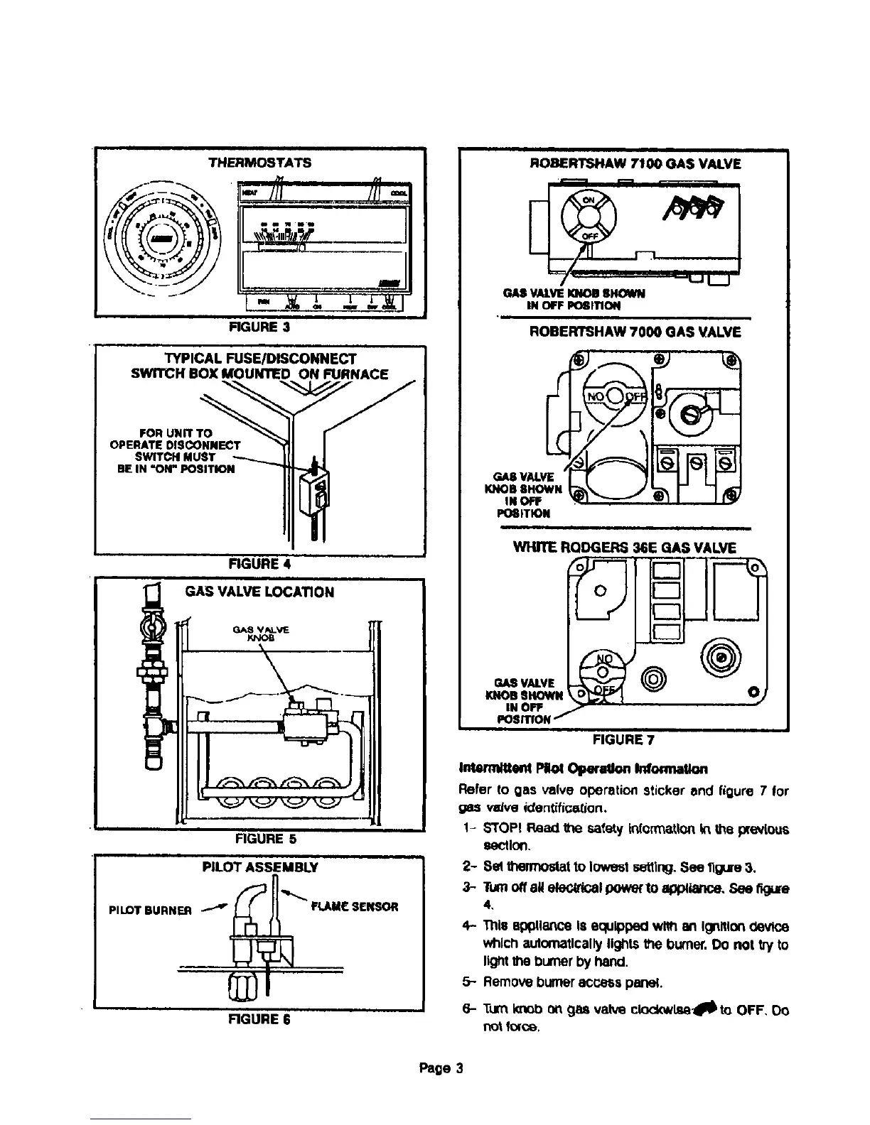
ROBERTSHAW 7100 GAS VALVE
GASVALVEKNOB8_
IN OFF L_ITION
ROBERTSHAW 7000 GAS VALVE
POGITION
WIgTE RQDGERS 36E GAS VALVE
GASVALVE )_
KNOBSHOWN O_
IN OFF " ----
POSrllON/
FIGURE 7
k_mduent PI_ O_xaOo. _ormaUo.
Refer to gas valve operation sticker and figure 7 for
gas veJveictentifice_ion.
1- s'roPI Read the safety Infom_atlonin the previous
section.
2- 8el lt_nTx_lat to lowest settlng.See 11gure3.
3- Turnoff8_ ete_dGal powe( to appllance. See figu[e
4,
4- Tills 8pl3tlol_'eISequipped wi#l oft IOrtitlon(levite
whichautomaticallylightsthe burner.Do not try to
lightthe l_umerby hand.
5- Remove burneraccess panel.
6- TurnKnot:)on gss valve clocl_l_l_to OFF, Do
not force,
Page 3
 Loading...