# 47860A005 Page 7
Concentric Vent Kit
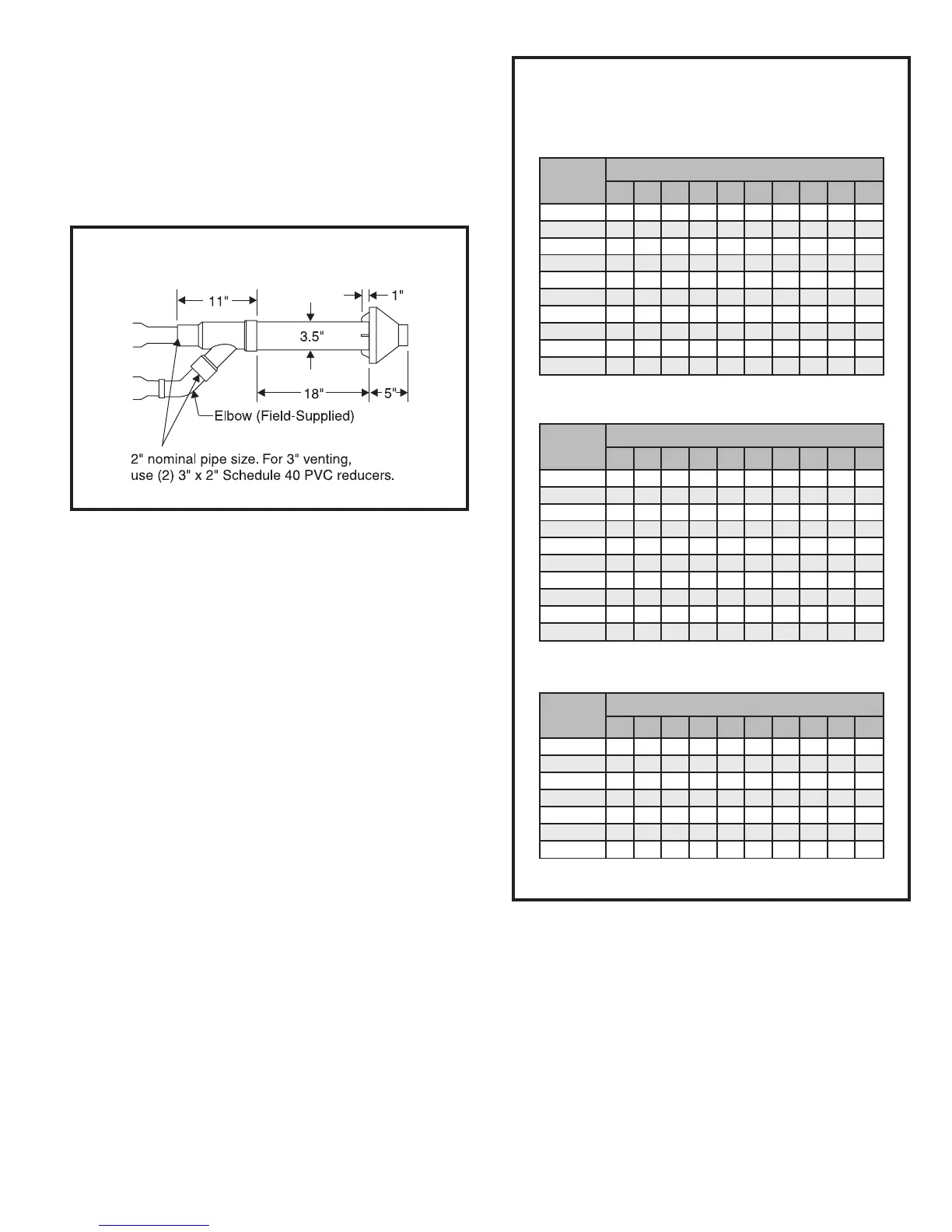
A concentric vent kit (model ACVK2) is available for use
when installing this furnace as a direct vent furnace and the
air intake and vent pipe are to be run through the same hole,
whether horizontally through the wall or vertically through the
roof (see Figure 3). Refer to the instructions included with
the concentric vent kit for installation specifics.
Vent Pipe Size and Length
The vent pipe and air intake pipe (in direct vent installa-
tions) should be sized in accordance with the information
found in the appropriate table in Figure 4. One 90° elbow
is equivalent to 5' of pipe. Two 45° elbows are equivalent
to one 90° elbow. The minimum length certified for use
with this furnace is 5' and one elbow, not including the
vent and air intake terminals.
In the event that the pipe length is in between the lengths
listed in the table, use the next larger length listed. For
example, if a length of pipe needed to install the furnace is
27', use the diameter values for the 30' row in the tables.
For direct vent installations, if the vent and air intake pipe
are not equal in length and number of elbows, then
determine the minimum pipe diameter for both the vent
and air intake. If the results indicate different diameters,
use the larger of the two for both the vent and air intake.
Under no circumstances should the vent and air
intake pipe size be different in diameter. For installation
details, refer to the appropriate section in pages 10 – 14
for the unit model and type of installation.
Horizontal Venting
The vent for this appliance shall not terminate over public
walkways; or near soffit vents or crawl space vents or
other areas where condensate or vapor could create a
nuisance or hazard or cause property damage; or where
condensate vapor could cause damage or could be
detrimental to the operation of regulators, relief valves, or
other equipment. See Figures 5 and 6 on pages 8 and 9 for
additional information on where the horizontal vent terminal
can and cannot terminate.
For horizontal venting in situations where clearance to
floor joists is limited, see Horizontal Venting – Low
Clearance Installations on page 14.
Figure 4
Vent Tables
(numbers in inches unless specified otherwise)
Minimum Pipe Diameter
40,000 – 80,000 BTU/HR Models
NR = Not Recommended
Minimum Pipe Diameter
112,000 – 125,000 BTU/HR Models
Minimum Pipe Diameter
90,000 – 100,000 BTU/HR Models
epiPtneV
htgneL
).tf(
swoblE°09forebmuN
0 1 2 3 4 5 6 7 8 9
5
5.15.1 22222222
01
5.1 2 2 2 2 2 2 2 2 2
02
222222222 5.2
03
2 2 2 2 2 2 2 5.2 5.2 5.2
04
22222 5.25.25.25.25.2
05
2 2 5.2 5.2 5.2 5.2 5.2 5.2 5.2 3
06
25.25.25.25.25.25.2 333
07
5.2 5.2 5.2 5.2 5.2 3 3 3 3 RN
08
5.25.25.2 33333 RNRN
09
5.2 5.2 3 3 3 3 3 RN RN RN
epiPtneV
htgneL
).tf(
swoblE°09forebmuN
0 1 2 3 4 5 6 7 8 9
5
RN 222222 5.25.25.2
01
2 2 2 2 2 2 5.2 5.2 5.2 5.2
02
22222 5.25.25.25.23
03
2 2 2 5.2 5.2 5.2 5.2 3 3 3
04
22 5.25.25.2 33333
05
5.2 5.2 5.2 3 3 3 3 3 3 RN
06
5.2 333333 RNRNRN
07
3 3 3 3 3 RN RN RN RN RN
08
333 RNRNRNRNRNRNRN
09
3 3 RN RN RN RN RN RN RN RN
epiPtneV
htgneL
).tf(
swoblE°09forebmuN
0 1 2 3 4 5 6 7 8 9
5
5.25.25.25.25.25.25.25.25.25.2
01
5.2 5.2 5.2 5.2 5.2 5.2 5.2 5.2 5.2 3
02
5.25.25.25.25.25.25.233RN
03
5.2 5.2 5.2 5.2 5.2 3 3 RN RN RN
04
5.25.25.25.23RNRNRNRNRN
05
5.2 3 3 RN RN RN RN RN RN RN
06
33 RNRNRNRNRNRNRNRN
Figure 3
Concentric Vent Kit Dimensions
 Loading...


