Vent
Height
H
(feet)
15
3O
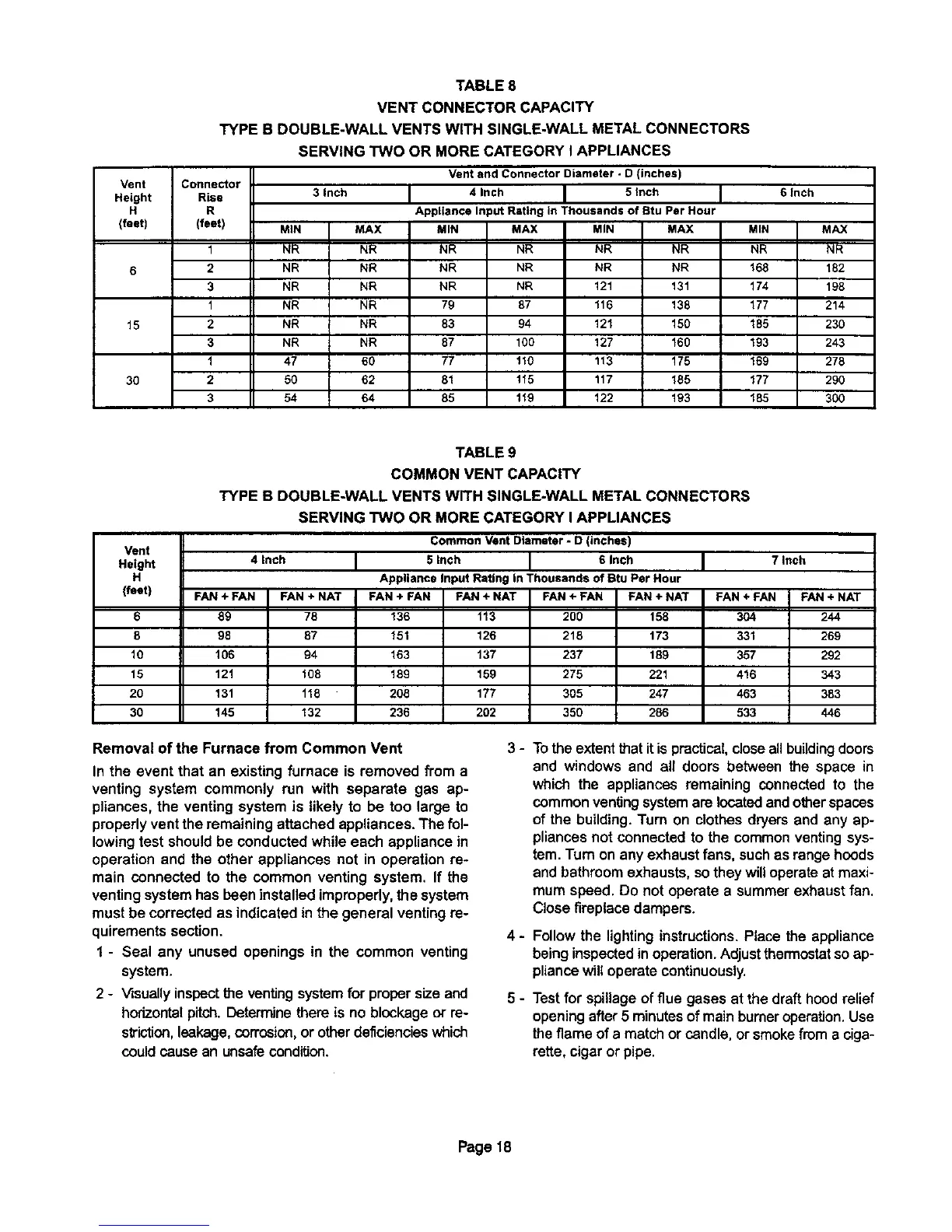
TABLE 8
VENT CONNECTOR CAPACITY
TYPE B DOUBLE-WALL VENTS WITH SINGLE-WALL METAL CONNECTORS
Connector
Rise
R
(feet)
1
2
3
1
2
3
1
2
3
SERVING TWO OR MORE CATEGORY I APPLIANCES
MIN
NR
NR
NR
NR
NR
NR
47
5O
54
3 Inch
MAX
NR
NR
NR
NR
NR
NR
6O
62
84
Vent and Connector Diameter - D (inches)
4 Inch 5 inch
Appliance Input Rating in Thousands of Btu Per Hour
MIN
NR
NR
NR
79
83
87
77
81
85
MAX MIN MAX
NR NR NR
NR NR NR
NR 121 131
87 116 138
94 121 150
100 127 160
110 113 175
115 117 185
119 122 193
MIN
NR
168
174
177
185
193
169
177
185
6Inch
MAX
NR
182
198
214
230
243
278
290
30O
Vent
Height
H
(feet)
6
8
10
15
2O
3O
TABLE 9
COMMON VENT CAPACITY
TYPE B DOUBLE-WALL VENTS WITH SINGLE-WALL METAL CONNECTORS
SERVING TWO OR MORE CATEGORY I APPLIANCES
Common Vent Diameter * D (inches)
4 inch
FAN+ FAN FAN + NAT
89 78
98 87
106 94
121 108
131 118
145 132
5 inch 6 Inch
Appliance Input Rating in Thousands of atu Per Hour
FAN + FAN
136
151
163
189
208
236
FAN + NAT
113
126
137
159
177
202
FAN + FAN
200
218
237
275
305
350
FAN ÷ NAT
158
173
189
221
247
286
FAN ÷ FAN
304
331
357
416
463
533
7Inch
FAN + NAT
244
269
292
343
383
446
Removal of the Furnace from Common Vent
In the event that an existing furnace is removed from a
venting system commonly run with separate gas ap-
pliances, the venting system is likely to be too large to
properly ventthe remaining attached appliances. The fol-
lowingtest shouldbe conducted while each appliance in
operation and the other appliances not in operation re-
main connected to the common venting system. If the
venting systemhas been installed improperly,the system
must be corrected as indicated in the general venting re-
quirements section.
1 - Seal any unused openings in the common venting
system.
2 - Visuallyinspecttheventingsystemfor propersizeand
horizontal pitch. Deterrrmethere is no blockage or re-
striction, leakage,corrosion, or other deficiencies which
could cause an unsafe condition.
3-
4-
5-
Tothe extentthat itis practical, closeallbuilding doors
and windows and all doors between the space in
which the appliances remaining connected to the
common ventingsystemare located andotherspaces
of the building. Turn on clothesdryers and any ap-
pliancesnot connected to the commonventingsys-
tem.Turn on any exhaust fans, suchas rangehoods
and bathroom exhausts, sothey willoperate at maxi-
mumspeed. Do not operate a summerexhaustfan.
Closefireplacedampers.
Follow the lightinginstructions. Place the appliance
being inspected in operation. Adjust thermostat so ap-
pliance will operate continuously.
Testfor spillageof flue gases at the draft hood relief
openingafter5 minutesof mainburner operation.Use
theflame of a matchorcandle, or smokefrom a ciga-
rette,cigar or pipe.
Page 18

 Loading...


