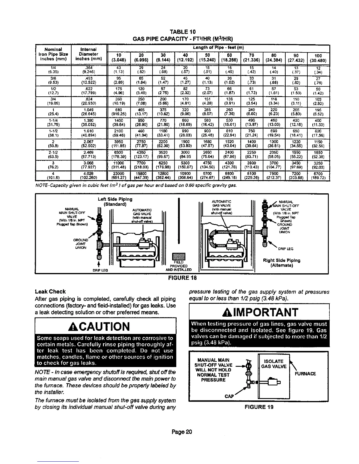
TABLE 10
GAS PIPE CAPACITY - FT3/HR (M3/HR)
Nominal Internal
Iron Pipe Size Diameter 10 20 30 i 40
inches (mm) inches (mm) (3.048) (6.096) (9.144) I (12.192
1/4 .364 43 29 24 20
(6.35) (9.246) (1113) (.52) (,65) (.57)
3/8 .493 96 65 52 45
(9.53) (12.522) (2.69) (t.84) (1.47) (1.27)
112 .622 175 t20 97 82
(12.7) (17.799) (4.95) (3.40) (2,75) (2.32)
3/4 .524 360 250 200 170
(19.05) (20.930) (10.t9) (7.08) (5,66) (4,81)
1 1.049 680 465 375 320
(25,4) (26.645) (919.25) (13.t7) (10.62) (9,06)
1-1/4 1,380 1400 950 770 660
(31.75) (38.052) (39.64) (26,90) (21.80) (18.69)
1-1/2 1.610 2100 460 tt80 990
(38,1) (40.894) (59A6) (41.34) (33,41) (26,03)
2 2,067 3950 2750 2200 1900
(50.8) (52.502} (111.85) (77,67) (62,30) (53,80)
2-1/2 2,469 6300 4350 3520 3000
(63,5) (67.713) (176.39) (123,17) (99.67) (84.95
3 3,068 11000 7700 6250 5300
(76.2) (77.927) (311.46) (216.03) (176.98) (150.07)
4 4.026 23000 15800 12800 10900
(101.6) (102.260) (65t.27) (447.39) (362,44) (308.64)
Length of Pipe - feet (m)
80 60 70 00 90 100
(15.240) (18.288) (21,336) (24.384) (27,432) (30.480)
18 16 15 14 13 12
(.51) (.45) (.42) (,40) (.37) (.34)
40 36 33 31 29 27
(1.13) (1.02) (.73) (.88) (,82) (.76)
73 66 61 57 53 50
(2.07) (1,87) (I,73) (1.61) (150) (1.42)
151 138 125 118 110 103
(4.28) (3.91) (3.54) (3,34) {3.11) (2.92)
285 260 240 220 205 195
(8,07) (7.36) (6.80) (623) (5.80) (5.52)
580 530 490 460 430 400
(16.42) (15.01) (13.87) (13.03) (12.18) (11.33)
900 810 750 690 650 620
(25,48) (22.94) [21.24) (19,54) (18.41) (17.56)
1680 1520 1400 1300 1220 1150
(47.57) (43,04) (39.64) (36,01) (34.55) (32,56)
2650 2400 2250 2050 1950 1850
(75.04) (67.96) (63.71) (58.05) (55,22) (52.38)
4750 4300 3900 3700 3450 3250
(134.50) (121.76) (110.43) (104.77) (97.69) (92.03)
9700 8600 8100 7500 7200 6700
(274,67) (249.13) (229,36) (212,37) (203,88) (189.72)
NOTE-Capacity given 3in cubic feet (m ) of gas per hour and based on O,6Ospecific grav_tygas.
MANUAL
MAIN SHUT-OFF
VALVE
(With I/6 _n.NPT "_I
Plugged Tap Shown)
JOINT
UNION
Left Side Piping
(Standard)
AUTOMATIC
GASVALVE
(v_t=manual
DRIPLEG
AUTOMATIC
GASVALVE
(withmanusl
valvai
FIELD
PROVIDED
ANDINSTALLED
FIGURE 18
MANUAL
VALVE
Plugged Tap
Shown)
JOLNT
UNtON
_DRIP LEG
Right Side Piping
(Alternate)
Leak Check
After gas piping is completed, carefully check all piping
connections(factory-andfield-installed) forgasleaks.Use
a leak detectingsolutionor otherpreferredmeans.
ACAUTION
NOTE - In case emergency shutoff is required,shutoffthe
main manual gas valveand disconnect the mainpowerto
the furnace. These devicesshouldbe properly labeledby
the installer.
The furnacemust be isolatedfrom the gas supplysystem
by closingits individualmanual shut-off valve duringany
pressure testing of the gas supply system at pressures
equalto or/ess than 1/2psig (3.48 kPa).
AIMPORTANT
MANUAL MAiN
SHUT,OFF VALVE
WILL NOT HOLD
NORMAL TEST
PRESSURE
c/_
ISOLATE
FIGURE 19
Page20

 Loading...


