HeatingSequenceOfOperation
1- Whenthermostatcallsforheat,combustionairblower
starts.
2 - Combustion air pressure switch proves blower opera-
tJon.Switch is factory set and requires no adjustment.
3 - After a 15 second prepurge, hot surface ignitor ener-
gizes.
4 - After a 20 second ignitor warm-up period, gas valve
solenoid opens.
5 - Gas is ignited, ignition sensor proves the flame and
combustion process continues.
6 - If flame is not detected after first ignition tdat, ignition
controlwillrepeat steps3 and4 fourmoretimesbefore
lockingoutthe gasvalve ("WATCHGUARD"flame fail-
ure mode). Ignitioncontrolwill then automaticallyre-
peat steps3, 4, 5 and 6 after 60 minutes,
7- To interruptthe 60-minute °WATCHGUARD" pedod,
move thermostat_om "Heat" to "OFF" then back to
"Heat." Heatingsequencethen restartsat step f.
: • :. . • . . :::_ • : . ,: :::_:_:: _:::::: ;}::;:_::: :::::: ;_:1;'_:_:::::
Gas Flow
Tocheck for propergasflow to thecombusf_onchamber,de-
terrninethe Bto(kW)klputfrom the unit ratingplate.Dividethis
inputraSngby theBtu (kW) per cubicfoot (cubicmeter)of
availablegas,The resultis therequirednumberof cubic feet
(cubicmeter)perhour.Determinetheflowof gas throughthe
gas meterfor two minutesend multiplyby 30 to getthe houdy
flowof gas.
Gas Pressure
1 - Check the gas line pressure withthe unitfiringat maxi-
mumrate.A minimum of 4.5 in.w.c.for naturalgas or
11.0in.w.c,forLP/prepanegasshouldbe maintained.
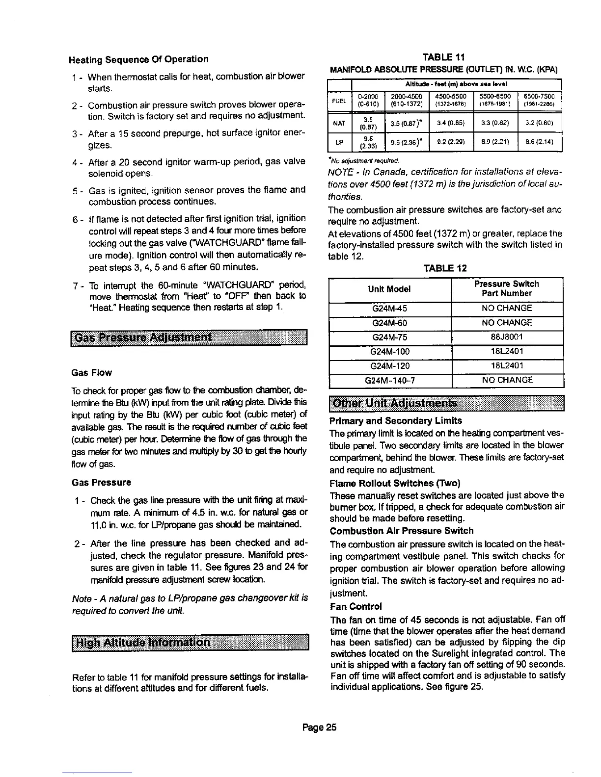
2- After the line pressure has been checked and ad-
justed, check the regulator pressure. Manifold pres-
suresare givenin table 11. See figures23 and 24 for
manifoldpressureadjustmentscrewlocation.
Note - A natura! gas to LP/propane gas changeover kit is
requiredto convert theunit.
Refer totable 11 for manifoldpressure settingsfor installa-
tionsat differentaltitudesandfor differentfuels.
TABLE 11
MANIFOLDABSOLUTEPRESSURE(OUTLET}IN. W,C,(KPA)
Altitude -feet (m) above sia level
0-2000 2000-4500 4500-5500 5500-6500 6500-7500
FUEL (0-610) (610-1372) (1372-1676) (1676-1981) (1981÷2286)
3.5 3.5 (0,87)* 3.4 (0.85) 3,3 (0.82) 3.2 (0.80)
NAT (0.87)
6.6 6.5 (2.36)" 92 (2/29) 8,9 (221) 8.6 (2.14)
LP (2.36)
*No adjustment required.
NOTE - In Canada, certification for installations at eleva-
tions over 4500 feet (1372 m) is the jurisdiction of local au-
thorities.
The combustion air pressure switches are factory-set and
require no adjustment.
At elevations of4500 feet (1372 m)or greater, replace the
factory-installed pressure switch with the switch listed in
table 12.
Unit Model
G24M-45
G24M-60
G24M-75
G24M-100
G24M-120
G24M-14_?
TABLE 12
Pressure Switch
Part Number
NO CHANGE
NO CHANGE
88J8001
18L2401
18L2401
NO CHANGE
Primary and Secondary Limits
The primarylimitis locatedon theheatingcompadmentves-
tibulepanel.Two secondarylimitsere locatedinthe blower
compartment,behind the blower.Theselimitsarefactory-set
andrequire no adjustment.
Flame Rollout Switches (Two)
These manuallyresetswitchesare locatedjust abovethe
burnerbox. Iftdpped,a check for adequatecombustion air
shouldbe made before resetting.
Combustion Air Pressure Switch
The combustion air pressureswitchis locatedonthe heat-
ing compartmentvestibule panel. This switchchecks for
proper combustion air blower operation before allowing
ignitiontrial,The switchis factory-setand requiresno ad-
justment.
Fan Control
The fan on time of 45 seconds is not adjustable. Fan off
time (time thatthe bloweroperates afterthe heatdemand
has been satisfied) can be adjusted by flippingthe dip
switcheslocated on the Surelightintegratedcontrol.The
unitis shippedwitha factoryfan offsettingof 90 seconds.
Fan off timewillaffect comfortand is adjustableto satisfy
individualapplications.See figure25.
Page25

 Loading...


