l_!_ _ _!_iiiiiiiiiiiiii!iiiiiiiiiiiiiii;i;;ilil;;il;illiiiiiiiii iili i i i!ii;iiiiii;i;i;iii!i;i!!;!iii!il;iii;ii;iiiiiiiiiiiiiiiiiiiiiiiiiiii!iiiiiii_iiii!i_i_Ji_%_
The following repairpartsare availablethroughindependentLennoxdealers. When ordenngparts, includethe coreplet_furnace model numberlistedon the
A.G.A. or C.G.A. rating plate -- Example: G24M3-75. Refer to page 3 for parts iderdification.
CABINET PARTS
Front acoess panel
Blower access panel
Cabinet cap
Cabinet bottom
Vent adapter
ELECTRICAL PARTS
Transformer
Controlboard (Hot Sudace Ignition)
Door interlock switch
BLOWER PARTS
Blower wheel
Motor
Blower housing cut-offplate
Motor capacitor
HEATING PARTB
Heat exchanger
Main burners
Main burner orifices
Gas manifold/Burnerbox assembly
Gas valve
NOx turbulator [60 Hz, X units only)
Hot Surface Ignitor
Flame roliout switch (two)
FJame sensor
Primary limit
Secondary limit (two)
Pressure switch
Wire harness plug il cap
Flue box
Combustionair blower
Gaskets
Low gas pressure switch (propane only)
_ -,,_,-.----.-.--- _ .-._--_.-- ___..-_ --.-_,K_----_--_ .-- _--_._............ ........................................................ : : ::::::::::::::::::::::::::::::::::::::::::::::::::::::::::::: :::::::;::::
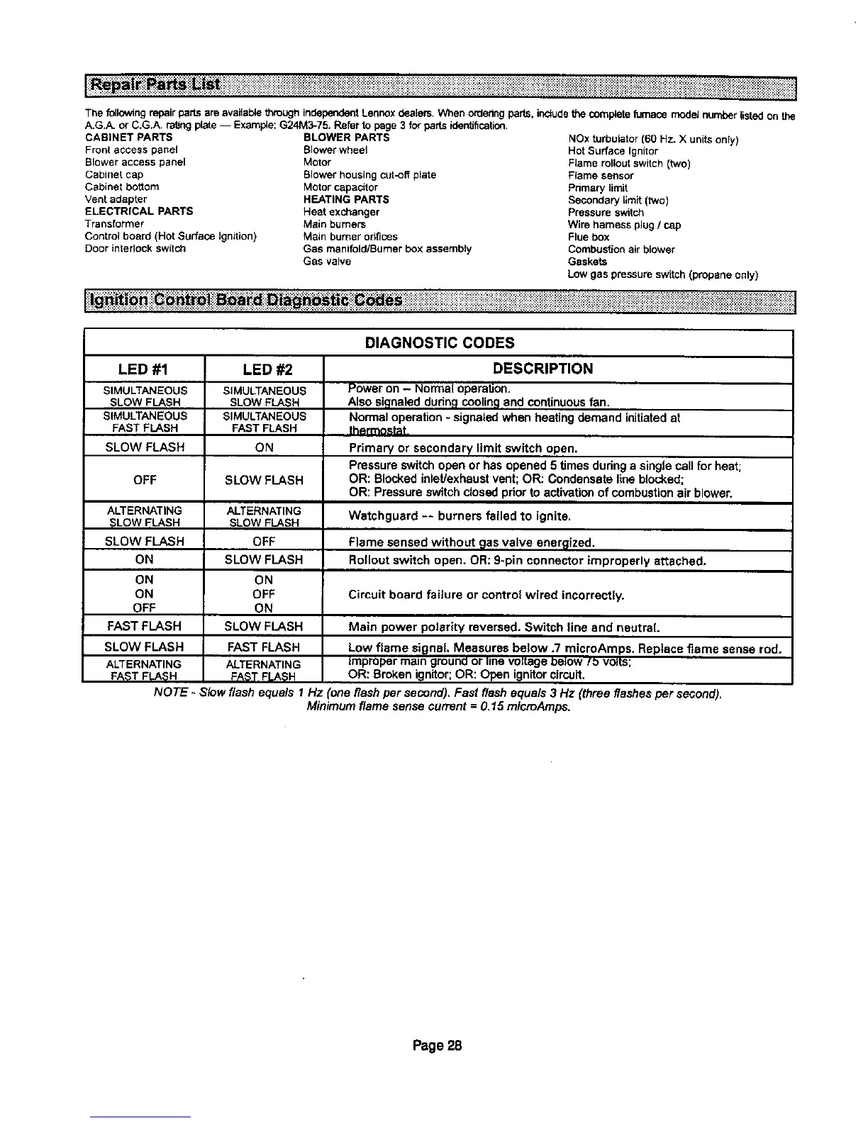
DIAGNOSTIC CODES
LED #1
SIMULTANEOUS
SLOW FLASH
SIMULTANEOUS
FAST FLASH
SLOW FLASH
OFF
ALTERNATING
SLOWFLASH
SLOW FLASH
ON
ON
ON
OFF
FAST FLASH
SLOW FLASH
ALTERNATING
FAST FLASH
LED #2
SIMULTANEOUS
SLOW FLASH
SIMULTANEOUS
FAST FLASH
ON
SLOW FLASH
ALTERNATING
SLOW FLASH
OFF
SLOW FLASH
ON
OFF
ON
SLOW FLASH
FAST FLASH
ALTERNATING
FAST FLASH
DESCRIPTION
Power on - Normal operation.
Also signaled dudn,qcoolingand continuousfan.
Normal operation- signaled when heating demand initiatedat
thermostat,
Primary or secondary limit switch open.
Pressure switchopen or has opened 5 times duringa single call for heat;
OR: Blocked inlet/exhaustvent; OR: Condensate lineblocked;
OR: Pressure switchclosed priorto activationof combustionair blower.
Watchguard -- burners failed to ignite.
Flame sensed without gas valve ensr_lized.
Rollout switch open. OR: 9-pin connector improperly attached.
Circuit board failure or control wired incorrectly.
Main power polariW reversed. Switch line and neutral.
Low flame signal Measures below .7 microAmps. Replace flame sense rod.
Improper main gmuna or linevoKageeelow/_ volts;
OR: Broken ignitor;OR: Open ignitorcircuit.
NOTE - Slow flash equals 1 Hz (one flash per second), Fast flash equals 3 Hz (three flashesper second).
Minimum flame sense current = 0.15 microAmps.
Page 28

 Loading...


