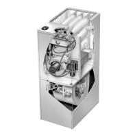
EasyManua.ls Logo

Lennox G26Q4/5-100 User Manual

Lennox G26Q4/5-100
52 pages
To Next Page IconTo Next Page
Page #1 background imageLoading...
Page #1 background image
LENNOXOEMPARTS.COM
FIGURE 1
G26 FURNACEY
AG26 HEAT EXCHANGE ASSEMBLY
Combustion Process:
1. A call for heat starts the combustion air blower.
2. Outdoorairisdrawnthroughpipeintotheburner
compartment where it mixes with gas in a con-
ventional style inshot burner.
3. TheSureLightignitionsystemlightstheburners.
4. Combustion products are drawn downward
through the heat exchanger. Heat is extracted
as indoor air passes across the outside surface
of the metal.
5. Latent heat is removed from the combustion
productsasairpassesthroughthecoil.Conden-
sate (water) is formed as the combustion prod-
ucts cool.
6. As the combustion products exit the coil, con-
densate is collected and drained away.
7. Combustion products are pulled from the heat
exchanger and forced into the flue.
7
5
4
6
2
3
1
Page 1
ã 1997 Lennox Industries Inc.
Litho U.S.A.
Corp. 9721-L11
G26
Service Literature
Revised 07-2001
G26 SERIES UNITS
G26 series units are high-efficiencyupflow gas furnaces manufactured with
DuralokPlust aluminized steel clamshell-type heat exchangers. G26 units
are available in heating capacities of 50,000 to 125,000 Btuh and cooling
applications up to 5 tons. Refer to Engineering Handbook for proper sizing.
Units are factory equipped for use with natural gas. A kit is available for con-
version to LPG operation. G26-1 and -2 model units use electronic (intermit-
tent pilot) ignition. G26-3, -4, -5 and -6 model units feature the Lennox Sur-
eLightT silicon nitride ignition system. Each unit meets the California Nitro-
gen Oxides (NO
x
) Standards and California Seasonal Efficiency require-
ments without modification. All units use a redundant gas valve to assure
safety shut-off as required by A.G.A. or C.G.A.
Information contained in this manual is intended for use by qualified service
technicians only. All specifications are subject to change. Procedures out-
lined in this manual are presented as a recommendation only and do notsu-
persede or replace local or state codes. In the absence of local or state
codes, the guidelines and procedures outlined in this manual (except where
noted) are recommended only.

Table of Contents

Other manuals for Lennox G26Q4/5-100

Question and Answer IconNeed help?

Do you have a question about the Lennox G26Q4/5-100 and is the answer not in the manual?

Lennox G26Q4/5-100 Specifications

General IconGeneral
Stages2
Fuel TypeNatural Gas
Input BTU100, 000
AFUE80%
AFUE Rating80%

Summary

G26 SERIES UNITS

SPECIFICATIONS

BLOWER PERFORMANCE DATA

G26Q2-50 BLOWER PERFORMANCE

Air volume and motor watt data for the G26Q2-50 model.

G26Q3-50 BLOWER PERFORMANCE

Air volume and motor watt data for the G26Q3-50 model.

G26Q3-75 BLOWER PERFORMANCE

Air volume and motor watt data for the G26Q3-75 model.

G26Q4/5-75 BLOWER PERFORMANCE

Air volume and motor watt data for the G26Q4/5-75 model.

INTAKE and EXHAUST PIPE VENTING TABLE

G26-3 THROUGH -6 COMPONENTS

6- SureLight Ignition System A3 (-3 through -6 models)

DIAGNOSTIC CODES

ELECTROSTATIC DISCHARGE (ESD) Precautions and Procedures

12-Ignition Control (-1 and -2 models)

Diagnostic LED

Johnson G776 Ignition Control Operation

15-Differential Pressure Switch (S64) (Combustion Air Prove Switch)

Condensate Piping

G26-3 THROUGH -6 MODEL CONDENSATE REMOVAL PROCESS

III-START-UP

A-Preliminary and Seasonal Checks

Steps for inspecting electrical wiring and condensate traps before startup.

B-Heating Start-Up

IV-HEATING SYSTEM SERVICE CHECKS

E-Testing Gas Supply Pressure

F-Check Manifold Pressure

I-Flame Signal

V-TYPICAL OPERATING CHARACTERISTICS

VI-MAINTENANCE

B-Cleaning Heat Exchanger and Burners

VII-WIRING DIAGRAM, SEQUENCE OF OPERATION &TROUBLESHOOTING

A-Field Wiring, Thermostat Connections

Diagram and explanation of field wiring and thermostat connections.

B-Wiring Diagram G26 (-3 & -4 Shown)

HEATING SEQUENCE OF OPERATION SURELIGHT CONTROL

COOLING SEQUENCE OF OPERATION SURELIGHT CONTROL

CONTINUOUS LOW SPEED FAN SEQUENCE OF OPERATION SURELIGHT CONTROL

D- SureLight Control Trouble Shooting Guide

PROBLEM 1: UNIT FAILS TO OPERATE IN THE COOLING, HEATING, OR CONTINUOUS FAN MODE

PROBLEM 3: UNIT FAILS TO FIRE IN THE HEATING MODE, COMBUSTION AIR BLOWER DOES NOT ENERGIZE

PROBLEM 4: UNIT FAILS TO FIRE IN THE HEATING MODE, COMBUSTION AIR BLOWER ENERGIZES, IGNITOR IS NOT ENERGIZED.

PROBLEM 5: UNIT FAILS TO FIRE IN THE HEATING MODE, COMBUSTION AIR BLOWER ENERGIZES, IGNITOR IS ENERGIZED. (CONT.)

PROBLEM 6: BURNERS LIGHT WITH A HEATING DEMAND BUT UNIT SHUTS DOWN PREMATURELY

PROBLEM 7: CONTROL SIGNALS LOW FLAME SENSE DURING HEATING MODE

PROBLEM 8: INDOOR BLOWER FAILS TO OPERATE IN COOLING, HEATING, OR CONTINUOUS FAN MODE

E-G26-1 and -2 Models

F-BCC2 Blower Control -1 and -2 Models

G776 IGNITION CONTROL TROUBLESHOOTING

G776 IGNITION CONTROL TROUBLESHOOTING -1 and -2 MODELS

Related product manuals