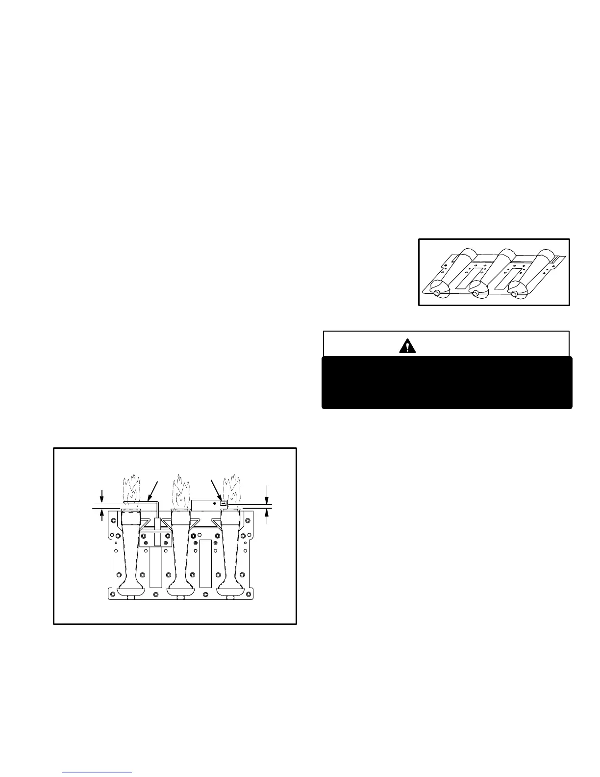
FIGURE 7
TYPICAL BURNER ASSEMBLY
Page 7
Integrated ignition and blower control components (A92),
unit transformer (T1) and 24V circuit breaker (CB8) are lo
cated in the control box. In addition, a door interlock switch
(S51) is located in the control box. Jackplugs allow the con
trol box to be easily removed for blower service.
1. Control Transformer (T1)
A transformer located in the control box provides power to
the low voltage 24volt section of the unit. Transformers on
all models are rated 40VA with a 120V primary and a 24V
secondary.
2. Circuit Breaker (CB8)
A 24V circuit breaker is also located in the control box. The
switch provides overcurrent protection to the transformer
(T1). The breaker is rated 3A at 32V. If the current exceeds
this limit the breaker will trip and all unit operation will shut
down. The breaker can be manually reset by pressing the
button on the face.
3.Door Interlock Switch (S51)
A door interlock switch rated 14A at 125VAC is located on
the control box. The switch is wired in series with line volt
age. When the blower door is removed the unit will shut
down.
4.Flame Sensor
A flame sensor is located on the left side of the burner sup
port. See figure 6. The sensor is mounted on a bracket in
the burner support and the tip protrudes into the flame en
velope of the left−most burner. The sensor is fastened to
burner supports and can be removed for service without re
moving any part of the burners. During operation, flame is
sensed by current passed through the flame and sensing
electrode. The SureLight control allows the gas valve to re
main open as long as flame signal is sensed.
FIGURE 6
SENSOR
IGNITOR
3/8"
5/16"
NOTE − The G32 furnace contains electronic compo
nents that are polarity sensitive. Make sure that the fur
nace is wired correctly and is properly grounded.
5.Burners
All units use inshot burners (see figure 7). Burners are factory
set and do not require adjustment. A sight glass is furnished
in the burner box assembly for flame viewing. Always
operate the unit with the burner box cover in place. Burn
ers can be removed as an assembly for service. Burner main
tenance and service is detailed in the MAINTENANCE sec
tion of this manual. Each burner uses an orifice which is pre
cisely matched to the burner input (see nameplate for orifice
size). The orifice is threaded into the burner manifold. The
burner is supported by the orifice and will easily slide off for
service. Each orifice and burner are sized specifically to the
unit. Refer to Lennox Repair Parts Listing for correct sizing
information. A flame retention ring in the end of each burner
maintains correct flame length and shape and keeps the flame
from lifting off the burner head. In addition, the burner entrance
to each clamshell is fitted with a corbel cup (orifice) used to
direct the flow of
combustion prod
ucts.
DANGER
Shock hazard.
Disconnect power before servicing. Control is not
field repairable. If control is inoperable, simply re
place entire control.
6.SureLight Ignition System A92
All G32−1 through −4 units are equipped with the Lennox
SureLight ignition system. The system consists of ignition
control board (figure 8 with control terminal designations
in table 1) and ignitor (figures 6 and 9). The board and igni
tor work in combination to ensure furnace ignition and ig
nitor durability. The SureLight integrated board controls
all major furnace operations. The board also features two
LED lights for troubleshooting (and two accessory termi
nals rated at (4) four amps. See table 2 for troubleshooting
diagnostic codes.
NOTE − Do not remove blower access panel to read Sur
elight LED lights. A sight glass is provided on the access
panel for viewing.
Tables 3 and 4 show jack plug terminal designations. Units
equipped with the SureLight board can be used with either
electronic or electro−mechanical thermostats without
modification. The SureLight ignitor is made of durable sili
con−nitride. Ignitor longevity is also enhanced by voltage
ramping by the control board. The board finds the lowest
ignitor temperature which will successfully light the burn
er, thus increasing the life of the ignitor.

 Loading...


