Page 31
TABLE 29
ELECTRONICALLY CONTROLLED BLOWER MOTOR
CCW ROTATION
Unit Volts Phase HP
G32V3 120 1
1
1/2
1G32V5 120
Internal Operation
Each time the controller switches a stator winding (figure 19)
on and off, it is called a pulse." The length of time each pulse
stays on is called the pulse width." By varying the pulse width
(figure 21), the controller varies motor speed (called pulse-
width modulation"). This allows for precise control of motor
speed and allows the motor to compensate for varying load
conditions as sensed by the controller. In this case, the control-
ler monitors the static workload on the motor and varies motor
rpm in order to maintain constant airflow (cfm).
The motor is equipped with 11 incremental taps which are driv-
en by the integral controller. The controller is capable of control-
ling three of the 11 taps.
The motor controller is driven by the VSP2−1, VSP3−1 or
two−stage variable speed SureLight control. The control
receives its demand (PWM signal or fixed 24 VAC or VDC
signal) from optional controls such as the Harmony zone con-
trol system, Efficiency Plus Humidity Control (CCB1) or a con-
ventional thermostat.
Motor rpm is continually adjusted internally to maintain
constant static pressure against the blower wheel. The control-
ler monitors the static work load on the motor and motor amp-
draw to determine the amount of rpm adjustment. Blower rpm
may be adjusted any amount in order to maintain a constant
cfm as shown in Blower Ratings Tables. The amount of adjust-
ment is determined by the incremental taps which are used
and the amount of motor loading sensed internally. The cfm re-
mains relatively stable over a broad range of static pressure.
Since the blower constantly adjusts rpm to maintain a specified
cfm, motor rpm is not rated. Hence, the terms blower speed"
and speed tap" in this manual, on the unit wiring diagram and
on blower B3 refer to blower cfm regardless of motor rpm.
When Harmony is used, speed taps are overridden and a
PWM signal generated by the Harmony controller continuously
varies motor speed based upon zone demands.
Initial Power Up
When line voltage is applied to B3, there will be a large inrush
of power lasting less than 1/4 second. This inrush charges a
bank of DC filter capacitors inside the controller. If the discon-
nect switch is bounced when the disconnect is closed, the dis-
connect contacts may become welded. Try not to bounce the
disconnect switch when applying power to the unit.
Motor Start-Up
When B3 begins start-up, the motor gently vibrates back and
forth for a moment. This is normal. During this time the elec-
tronic controller is determining the exact position of the rotor.
Once the motor begins turning, the controller slowly eases the
motor up to speed (this is called soft-start"). The motor may
take as long as 10-15 seconds to reach full speed. If the motor
does not reach 200rpm within 13 seconds, the motor shuts
down. Then the motor will immediately attempt a restart. The
shutdown feature provides protection in case of a frozen bear-
ing or blocked blower wheel. The motor may attempt to start
eight times. If the motor does not start after the eighth try, the
controller locks out. Reset controller by momentarily turning off
power to unit.
The DC filter capacitors inside the controller are connected
electrically to the speed tap wires. The capacitors take
approximately 5 minutes to discharge when the disconnect
is opened. For this reason it is necessary to wait at least 5
minutes after turning off power to the unit before attempt-
ing to change speed taps.
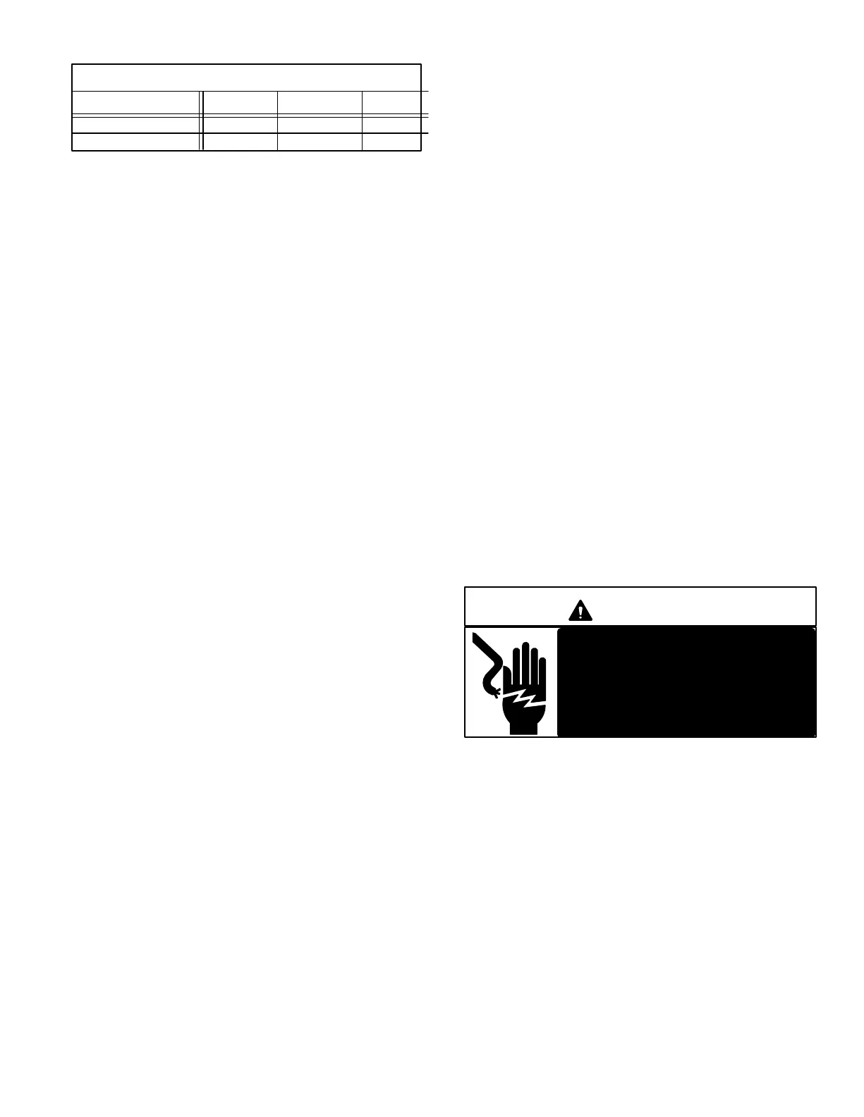
DANGER
Disconnect power from unit and
wait at least five minutes to allow
capacitors to discharge before at-
tempting to adjust motor speed tap
settings. Failure to wait may cause
personal injury or death.

 Loading...


