Page 50
VI−MAINTENANCE
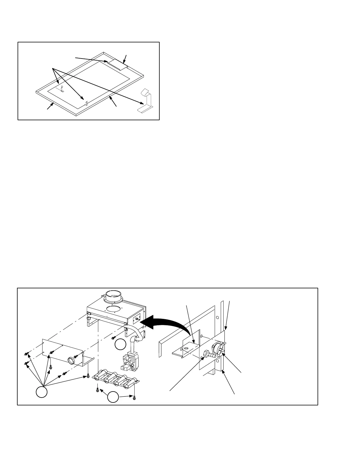
Retainers for factory supplied return air filter are shown in
figure 54.
FIGURE 54
BOTTOM RETURN FILTER
FURNACE
BASE BOTTOM
REAR FILTER CLIP
RETURN AIR
OPENING
SIDE FILTER CLIPS (2)
FURNACE
FRONT
FURNACE
BACK
A−Filters
At the beginning of each heating season, the system should
be checked as follows:
1 − Filters should be inspected monthly and must be
cleaned or replaced when dirty to ensure proper fur-
nace operation.
2 − Reusable foam filters used with the G32V can be
washed with water and mild detergent. When dry, they
should be sprayed with filter handicoater prior to rein-
stallation. Filter handicoater is RP Products coating no.
418 and is available as Lennox part no. P-8-5069.
3 − If replacement is necessary, order Lennox part no.
31J81 for 14" x 25" (356 x 635mm) filter for
G32VQ3−75 units and P-8-7831 for 20" x 25" (508 x
635mm) filter for G32V−100 and -125 units.
B−Cleaning Heat Exchanger and Burners
If cleaning the heat exchanger becomes necessary, follow
the below procedures and refer to figure 1 when disassem-
bling unit. Use papers or protective covering in front of fur-
nace while removing heat exchanger assembly.
1 − Turn off electrical and gas power supplies to furnace.
2 − Remove upper and lower furnace access panels.
3 − Remove four (4) screws around air intake fitting and lift
intake pipe up and away.
4 − Loosen hose clamp securing top of flue transition to
bottom of flue collar. Remove screw securing flue col-
lar to top cap and lift exhaust pipe and flue collar up and
away.
5 − If electrical field make up box is located inside the unit,
it must be removed.
6 − Remove gas supply line to connected to gas valve.
7 − Mark all gas valve wires and disconnect them from
valve. Mark and remove wires from flame roll-out
switch.
8 − Remove top cap of unit.
9 − Remove sensor wire from SureLight control. Discon-
nect 2-pin plug from the ignitor.
10− Mark and disconnect pressure switch tubing from both
sides of the pressure switch.
11− Loosen two (2) screws holding gas manifold support at
vestibule panel.
12− Remove four (4) burner box screws at the vestibule
panel and remove burner box and gas valve/manifold
assembly with bracket.
13− Drain condensate trap. Disconnect condensate line
from the outside of unit. Remove condensate line from
condensate trap by turning the adapter fitting counter-
clockwise. The fitting has standard right hand threads.
14− Disconnect the drain hose from the flue transition to
the elbow on the cold header (collector) box trap.
15− Disconnect the 3-pin plug from the combustion air
blower at the blower deck. Remove four (4) screws
from combustion air blower and remove flue transition
and blower assembly from cabinet. Take care not to
lose the combustion air orifice.
FIGURE 55
Simplified Burner Removal:
1− Remove cover by loosening bot-
tom screws (2) and removing
cover front screws (5).
2− Remove ignitor wire and sensor
wire. Remove gas valve and
manifold assembly.
3− Remove burner assembly.
BURNER ACCESS/REMOVAL
2
3
1
BARBED PRESSURE
SWITCH FITTINGS
BURNER MOUNTING
BRACKET
PATCH PLATE
UNIT VEST PANEL
ROLLOUT SWITCH

 Loading...


