Page 17
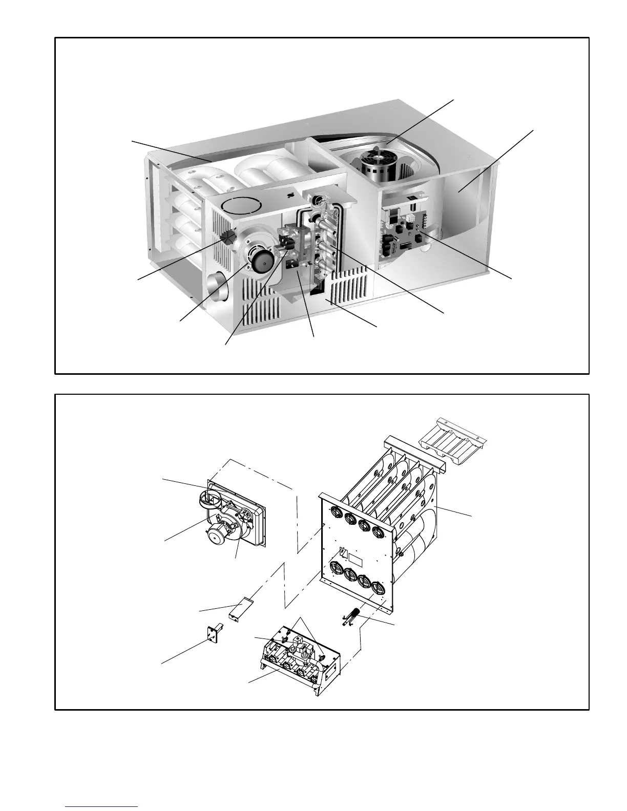
FIGURE 2
G50UH(X) PARTS IDENTIFICATION
(HORIZONTAL POSITION)
BLOWER
ACCESS PANEL
HEAT EXCHANGER ASSEMBLY
BURNER
ASSEMBLY
COMBUSTION AIR
INDUCER
CONTROL
BOARD
PROVE
SWITCH
GAS VALVE
BURNER
ACCESS PANEL
BLOWER ASSEMBLY
PRIMARY LIMIT
FIGURE 3
G50UH (X) HEATING COMPONENTS
COMBUSTION AIR INDUCER
PROVE SWITCH
PRIMARY LIMIT
PRIMARY LIMIT SHIELD
GAS VALVE
ROLLOUT SWITCHES*
MANIFOLD/BURNER
ASSEMBLY
NO
x
Insert
(NO
x
Units Only)
HEAT EXCHANGER
FLUE COLLECTOR BOX
*135 and 155 kBtuh units only −−
Flame rollout switches are located
on brackets on the inner sides (one
on the left and one on the right) of
the burner box.
Air Deflector
ALL G50UH−48C−135,
ALL G50UH−36C−110.
ALL G50UH−60D−155 &
G50UH−60C−110−1, −2, −3
Units Only
 Loading...