Page 19
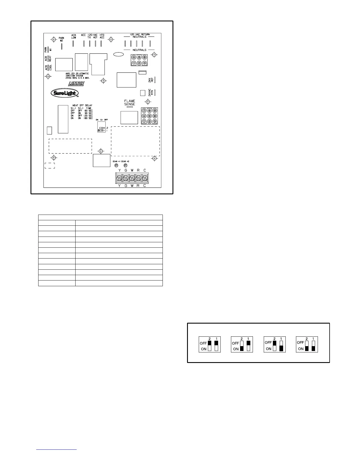
SURELIGHT INTEGRATED CONTROL BOARD
FIGURE 6
J58
J156
TABLE 1
SURELIGHT CONTROL TERMINAL DESIGNATIONS
ACB COOL
ACB HEAT
PARK
ACB LOW
ACC
TX
HOT
HTG ACC
NEUTRALS
24VAC HOT
24VAC RTN
FLAME SENSE
Blower − Cooling Speed (Line Volt)
Blower − Heating Speed (Line Volt)
Alternate Blower Speeds (Dead)
Continuous Low Speed Blower
Accessory Terminal (Line Volt)
120VAC Hot to Transformer
120VAC Hot Input
Heat Only Accessory (Line Volt)
120VAC Neutrals
24VAC Hot from Transformer
24VAC Return from Transformer
Flame Sense Terminal
a−Electronic Ignition (See Figure 9)
On a call for heat the SureLight control monitors the com-
bustion air inducer prove switch. The control will not begin
the heating cycle if the prove switch is closed (by−passed).
Once the proving switch is determined to be open, the
combustion air inducer is energized. When the differential
in the prove switch is great enough, the prove switch
closes and a 15−second pre−purge begins. If the prove
switch is not proven within 2−1/2 minutes, the control goes
into Watchguard−Pressure Switch mode for a 5−minute re−
set period.
After the 15−second pre−purge period, the SureLight igni-
tor warms up for 20 seconds during which the gas valve
opens at 19 seconds for a 4−second trial for ignition. Units
with control 56L83: ignitor stays energized for the first sec-
ond of the 4−second trial. Units with control 97L48: ignitor
stays energized during the 4−second ignition trial until
flame is sensed. If ignition is not proved during the 4−sec-
ond period, the control will try four more times with an inter
purge and warm−up time between trials of 35 seconds. Af-
ter a total of five trials for ignition (including the initial trial),
the control goes into Watchguard−Flame Failure mode. Af-
ter a 60−minute reset period, the control will begin the igni-
tion sequence again.
The SureLight control board has an added feature that pro-
longs the life of the ignitor. After a successful ignition, the
SureLight control utilizes less power to energize the ignitor
on successive calls for heat. The control continues to ramp
down the voltage to the ignitor until it finds the lowest
amount of power that will provide a successful ignition.
This amount of power is used for 255 cycles. On the 256th
call for heat, the control will again ramp down until the low-
est power is determined and the cycle begins again.
b−Fan Time Control
The fan on time of 45 seconds is not adjustable. Fan off
time (time that the blower operates after the heat demand
has been satisfied) can be adjusted by flipping the dip
switches located on the SureLight integrated control. The
unit is shipped with a factory fan off setting of 90 seconds.
Fan off time will affect comfort and is adjustable to satisfy
individual applications. For customized comfort, monitor
the supply air temperature once the heat demand is satis-
fied. Note the supply air temperature at the instant the
blower is de−energized. Adjust the fan−off delay to achieve
a supply air temperature between 90° − 110° at the instant
the blower is de−energized. (Longer delay times allow for
lower air temperature, shorter delay times allow for higher
air temperature). See figure 7.
FIGURE 7
FAN-OFF TIME ADJUSTMENT
To adjust fan−off timing, flip dip switch to desired setting.
60sec. 90sec. 120sec. 180sec.
 Loading...