Page 1
© 2003 Lennox Industries Inc.
Litho U.S.A.
Corp. 0307−L5
G51MP
Service Literature
Revised 9−2007
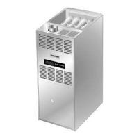
G51MP SERIES UNITS
G51MP series units are high−efficiency multiple position
(upflow, downflow, horizontal left and horizontal right)
gas furnaces manufactured with Lennox DuralokPlust
aluminized and stainless steel clamshell-type heat ex-
changers. G51MP units are available in heating input ca-
pacities of 44,000 to 132,000 Btuh (13 to 38.6 kW) and cool-
ing applications from 2 through 5 tons (7.0 through 17.6 kW).
Refer to Engineering Handbook for proper sizing.
Units are factory equipped for use with natural gas. A kit is
available for conversion to LPG operation. All G51MP units
are equipped with the Lennox SureLight
®
hot surface igni-
tion system. The gas valve is redundant to assure safety
shut−off as required by C.S.A.
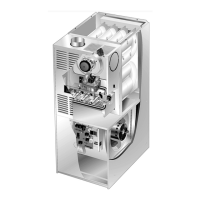
The heat exchanger, burners and manifold assembly can be
removed for inspection and service. The maintenance section
gives a detailed description on how this is done.
Information contained in this manual is intended for use by
qualified service technicians only. All specifications are sub-
ject to change. Procedures outlined in this manual are pre-
sented as a recommendation only and do not supersede or
replace local or state codes.
Table of Contents
General 1. . . . . . . . . . . . . . . . . . . . . . . . . . . . . . . . . . . . . .
Specifications 2. . . . . . . . . . . . . . . . . . . . . . . . . . . . . . . . .
Blower Performance Data 4. . . . . . . . . . . . . . . . . . . . . .
I−Unit Components 9. . . . . . . . . . . . . . . . . . . . . . . . . . . .
II Placement and Installation 19. . . . . . . . . . . . . . . . . . . .
III−Start−Up 33. . . . . . . . . . . . . . . . . . . . . . . . . . . . . . . . . . .
IV−Heating System Service Checks 34. . . . . . . . . . . . . .
V−Typical Operating Conditions 38. . . . . . . . . . . . . . . . .
VI−Maintenance 39. . . . . . . . . . . . . . . . . . . . . . . . . . . . . . .
VII−Wiring and Sequence of Operation 42. . . . . . . . . . .
VIII−Troubleshooting 48. . . . . . . . . . . . . . . . . . . . . . . . . . .
IMPORTANT
Improper installation, adjustment, alteration, service
or maintenance can cause property damage, person-
al injury or loss of life. Installation and service must
be performed by a qualified installer, service agency
or the gas supplier.
WARNING
Electric shock hazard. Can cause injury
or death. Before attempting to perform
any service or maintenance, turn the
electrical power to unit OFF at discon-
nect switch(es). Unit may have multiple
power supplies.
WARNING
Sharp edges.
Be careful when servicing unit to avoid sharp edges
which may result in personal injury.