Page 11
CONDENSER FAN
(top of unit - not shown)
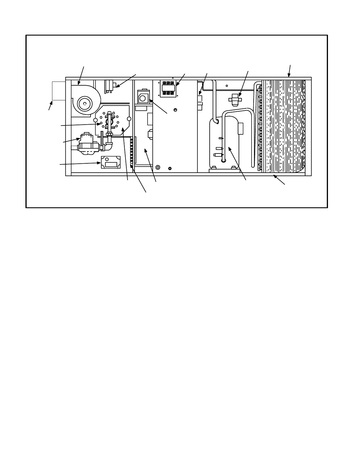
FIGURE 3
CONDENSER
GCS16-510/650 PARTS ARRANGEMENT
GCS16R-511/651 PARTS ARRANGEMENT
VENT CAP
IGNITION
CONTROL
BURNER
GAS VALVE
BLOW
ER
LIMIT
COMPRESSOR
COMPARTMENT
CONTROL BOX
COMBUSTION AIR
PROVE SWITCH
COMBUSTION AIR BLOWER
CONTACTOR
BURNER ENCLOSURE
GCS16-510/650-125 only
(not shown)
(see figure 12)
TB1 TERMINAL STRIP
(commercial units only)
FAN
CAPACITOR
COMPRESSOR
RUN
CAPACITOR
I-APPLICATION
GCS16 2-5 ton units are available in three model and
three cabinet sizes (refer to the Engineering Handbook for
more specific application data). GCS16H models are
available only in the smallest cabinet and are applicable
for residential installations with horizontal supply and dis
charge air only. GCS16H units are singlephase only and
are not equipped for installation of Lennox' optional ther
mostat control systems. GCS16R models are residential
only units available in both the small and large convertible
(downflow or horizontal) cabinets. GCS16R models, like
the GCS16H models, are singlephase only and are not
equipped for installation of Lennox' optional thermostat
control systems. GCS16 models are residential or com
mercial units available in single or threephase and avail
able in both the small and large convertible (downflow or
horizontal) cabinets. GCS16 models are factory equipped
with the hardware required for installing Lennox' optional
thermostat control systems. Lennox' optional thermostat
control systems are the same controls, harnesses, and
harness plugs used in GCS16 71/2 ton and larger units.
For example, a Honeywell W973 control will plug in to a
GCS16-411 as easily as it will plug in to a GCS16-1853
(and no field wiring is required for either).
II-UNIT COMPONENTS
GCS16 unit components are shown in figures1, 2 and 3.
A-Control Box Components
GCS16H control box is shown in figure 4. The control box
is located in the upper portion of the compressor compart
ment behind the compressor compartment access panel.
Note that the burner ignition control is located inside the
control box (not in the heating compartment). The con
denser fan has its own access panel located on the oppo
site side of the unit.
GCS16R-411 and GCS16-410 control box is shown in fig
ure 5. GCS16R-511/651 and GCS16-510/650 control box
is shown in figure 6. In both units, the control box is lo
cated in the heating compartment behind the heating
compartment access panel. Note that the compressor
contactor is located behind a separate access panel on
the mullion adjacent to the compressor compartment ac
cess panel. The condenser fan can be accessed by re
moving the fan grill located on top of the unit.
The indoor blower access panel (all units) is located on the
opposite side of the unit from the heating compartment ac
cess. Figure 1 shows typical blower compartment access.
 Loading...