Page 34
6-Replace gasket and reassemble (reverse steps
1-5). Be sure to secure all wires and check plumb
ing and burner plate for airtight seal. Bolts must be
torqued to 35 inlbs. to ensure proper operation.
7-Turn on power to unit.
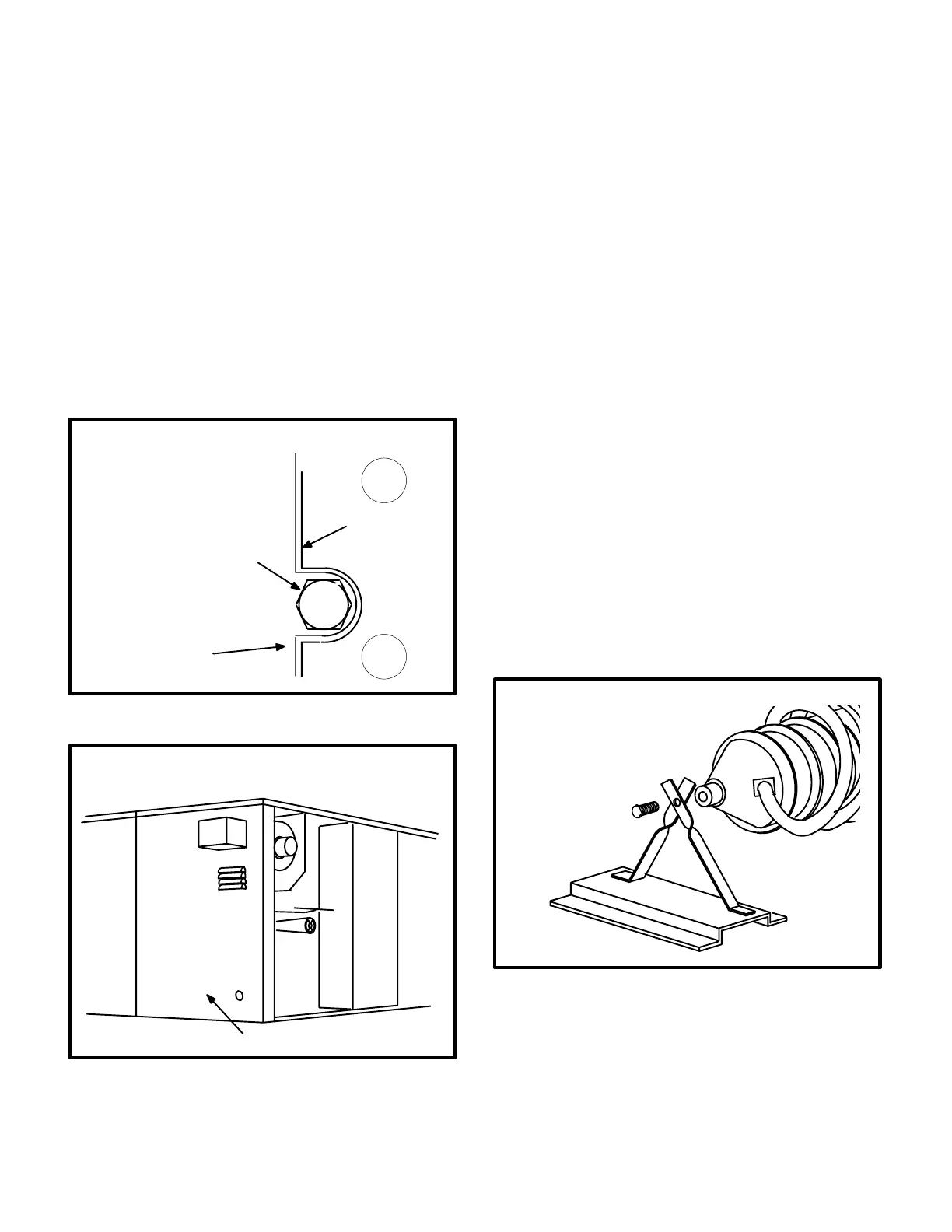
K-Heat Exchanger
WARNING - WHEN SERVICING THE BURNER, DO
NOT REMOVE THE BOLTS IN THE BURNER
PLATE SLOTS (SEE FIGURE 32). THESE BOLTS
SUPPORT THE HEAT EXCHANGER CASTING. RE
MOVAL OF THESE BOLTS WILL ALLOW THE
HEAT EXCHANGER TO DROP INSIDE THE CAB
INET AND COULD RESULT IN HEAT EXCHANGER
DAMAGE.
FIGURE 32
BURNER PLATE
BOLTS IN BURNER PLATE SLOTS
SUPPORT HEAT EXCHANGER
ONLY. DO NOT REMOVE UNLESS
REMOVING HEAT EXCHANGER.
GCS16 SERIES BURNER PLATE
GASKET
(BEHIND PLATE)
FIGURE 33
ACCESS TO HEAT EXCHANGER
GCS16 AND GCS16R
REMOVE UNIT END PANEL
To Access or Remove Heat Exchanger From Unit:
1-Turn off gas and electric power.
2-Remove cabinet end panel (see figure 33).
3-Remove combustion air blower and flue box. Pay
careful attention to the order in which gaskets and
orifice are removed.
4-Remove bolt in back of casting (see figure 34).
5-Remove bolts supporting heat exchanger in burner
plate (see figure 32).
6-Support heat exchanger (to prevent heat exchang
er from dropping when final bolts are removed.)
Remove bolts securing tailpipe to heating vesti
bule. Bolts are located behind flue box cover.
7-To install heat exchanger, reverse procedure.
Burner cone should be replaced when heat ex
changer is replaced. Be sure to secure all wires
and check plumbing and burner plate for airtight
seal. Bolts must be torqued to 35 inlbs. to ensure
proper operation.
CAUTION - AFTER UNIT HAS BEEN OPERATED,
BURNER CONE CAN BE EASILY DAMAGED BY
HANDLING. IT MUST BE HANDLED CAREFULLY.
CONE MUST BE REPLACED IF EITHER INSIDE OR
OUTSIDE EDGE ARE DAMAGED. A DAMAGED IN
SIDE EDGE CAN CAUSE IMPROPER OPERATION.
A DAMAGED OUTSIDE EDGE CAN CAUSE EX
HAUST PRODUCTS TO ENTER LIVING SPACE.
DO NOT ALLOW UNIT TO OPERATE WITH A DAM
AGED BURNER CONE.
FIGURE 34
REMOVE BOLT FROM CAST
ING. BE CAREFUL NOT TO
DROP HEAT EXCHANGER.
HEAT EXCHANGER REMOVAL
L-Ignition (Burner) Control A3
Ignition control A3 is factory set and is not adjustable. The
control makes three attempts at ignition and then locks out
the system if ignition is not obtained after the third trial.
Reset after lockout requires only breaking and remaking
thermostat demand. The control shuts off gas flow imme
 Loading...