Page 68
FIGURE 88
COMMERCIAL CONTROLS
MOUNTING BOX
PIANO HINGE
(use existing
screw holes)
CONTROLS MOUNTING BOX
1/4 TURN
FASTENER
RETURN AIR
OPENING
SUPPLY AIR
OPENING
FIGURE 89
COMMERCIAL CONTROLS MOUNTING BRACKET
BLOWER
VERTICAL RETURN
AIR OPENING
FACTORY FURNISHED
RETURN AIR COVER
CONTROLS
MOUNTING
BRACKET
UNIT
FLANGE
COVER
a
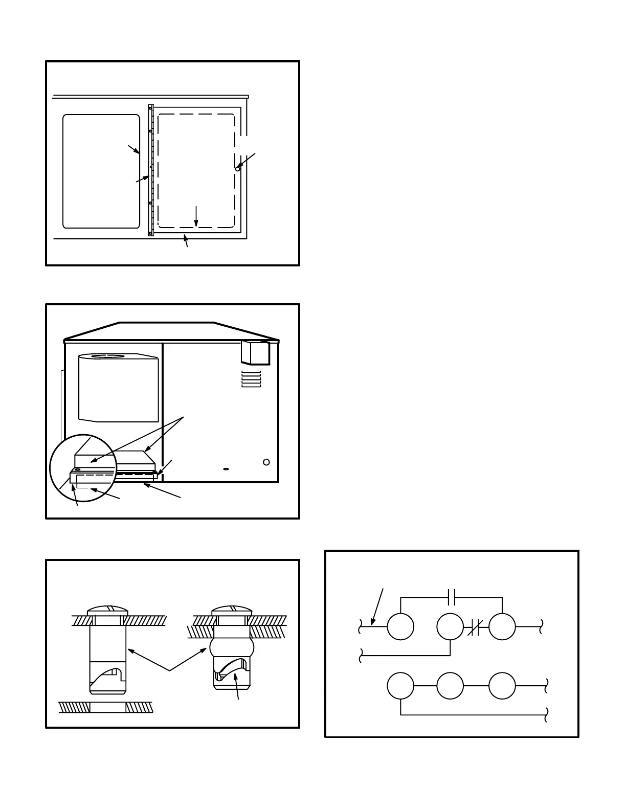
FIGURE 90
COMMERCIAL CONTROLS BOX
QUARTERTURN FASTENER
RUBBER
COMPRESSION
SEAL
RELEASED (OPEN) COMPRESSED (SEALED)
COMPRESSION
CAM
The box is fully insulated and a gasket around the enclo
sure flange provides an airtight seal. When servicing the
controls or blower, make sure the seal and insulation are in
good condition and make sure the seal is making an air
tight connection with the cabinet. The controls box is fas
tened to the cabinet with a quarterturn fastener. The fas
tener seals with a rubber ring which compresses around
the inside of the opening to provide an airtight seal. Figure
90 shows the quarterturn fastener.
V-Clocks / Timers (CMC3-1)
Two optional clocks (both designated model# CMC3-1)
are available for use with either the electromechanical
thermostat or the Honeywell W973 control system. Both
allow mechanical thermostats to set back during unoccu
pied periods. The clocks, models 202A and 702A, allow
24hour and 7day programmability, respectively.
Other GCS16 control system options (W7400, T7300,
Pro-stat, etc.) are equipped with builtin clocks for this pur
pose and do not need CMC3-1.
Both CMC3-1 clocks are alike except for programmability.
The clocks are rated 24VAC*, 60Hz and have SPDT con
tacts rated at 15A and 120VAC.
*NOTE - Some clocks may be 120VAC while most are
24VAC. Be sure to check clock motor rating and wire
clock according to its rating.
Wiring connections should be made to N.O. terminal 1 and
3 (see figure 91). Refer to the sequence of operation for
the control system being used (back of this manual) for
correct wiring connections. Refer to the Status Panel"
section of this manual for wiring connections of clocks
used with SP11 or SSP11. Refer to the manufacturer's op
eration and installation instructions printed inside the front
cover of each clock.
FIGURE 91
CMC3-1 TIME CLOCK
FIELD WIRING
120V
120V
TO TB1 TERMINAL 6*
TO TB1 TERMINAL 11
LINE
FRONT
TERMINALS
TIME CLOCK
REAR TERMINALS
12 3
13
*IF SSP11 IS USED CONNECT TO SSP11 TERMINAL 20
 Loading...