Page 21
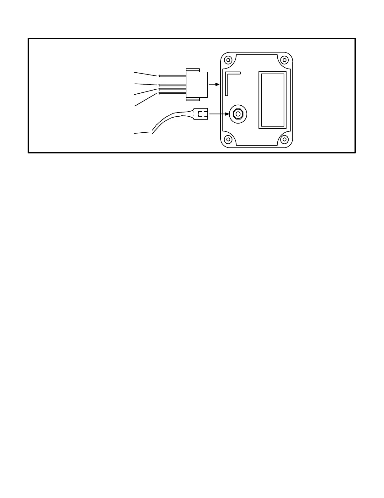
FIGURE 18
SPARK
HIGH VOLTAGE
POWER (24VAC INPUT)
TO GAS VALVE (24VAC OUTPUT)
TO FLAME SENSOR
GROUND
TOP VIEW
FENWAL IGNITION CONTROL
13-Electrode Assembly
The spark electrode/flame sensor assembly fits through a
hole in the burner plate. The electrode tips are located in
the path of the burner flame between the burner head and
the flame spreader. The electrode assembly is fastened to
the burner plate and can be removed for service without
removing any part of the burner assembly (except in units
with burner enclosure.)
During ignition spark travels through the spark electrode
and arcs across to the ground electrode. During operation,
flame is sensed by a current passed along the ground
electrode, through the flame and into the sensing elec
trode.
a-Spark Electrode
The spark electrode is connected to the ignition control
by a 5mm silicone insulated stranded high voltage
wire. The wire uses 1/4" female quick connect on the
electrode end and female spark plugtype terminal on
the ignition control end.
NOTE - IN ORDER TO MAXIMIZE SPARK ENER
GY TO THE ELECTRODE, THE HIGH VOLTAGE
WIRE SHOULD NOT REST ON THE BOTTOM
OF UNIT VESTIBULE PANEL AND SHOULD
TOUCH UNIT CABINET AS LITTLE AS POS
SIBLE.
b-Flame Sensor
Flame is sensed by rectification through the flame
sensing electrode.
14-Ignition Control A3
In GCS16H units, ignition control A3 is located in the unit
control box. In GCS16R and GCS16 units, ignition control
A3 is located in the heating compartment. On a heating
demand, the ignition control is energized after proving
combustion air blower operation. The control allows 30 to
40 seconds for the combustion air blower to vent exhaust
gases from the burner. The ignition control then activates
gas valve GV1, the spark electrode, the flame sensing
electrode and blower delay relay K25. The ignition control
is not adjustable.
WARNING - SHOCK HAZARD. SPARK RELATED
COMPONENTS CONTAIN HIGH VOLTAGE WHICH
CAN CAUSE PERSONAL INJURY OR DEATH. DIS
CONNECT POWER BEFORE SERVICING. CON
TROL IS NOT FIELD REPAIRABLE. UNSAFE OP
ERATION WILL RESULT. IF THE CONTROL IS IN
OPERABLE, SIMPLY REPLACE THE ENTIRE CON
TROL.
a- An electronic direct spark ignition with flame rectifi
cation sensing is used on all GCS16 units. Flame
signal strength ranges from 8 to 20 microamps.
All units have controls manufactured by Fenwal.
b- The Fenwal control is illustrated in figure 18. The
fourwire harness, plugged directly into a jack on
the side of the control, is used to connect the con
trol to the unit. Each of the four jack terminals is
identified by function. The spark electrode wire
connects to the spark plugtype connector on top
of the control.
c- The ignition control provides three main functions:
gas valve control, ignition and flame sensing. It is
powered only after the combustion air prove
switch has closed. The ignition attempt sequence
provides three trials for ignition before locking out.
The blower control (K25) is energized simulta
neously with the gas valve, so the blower will ener
gize 30 to 45 seconds after flame has successfully
been established. The unit will usually ignite on the
first attempt. See figure 19 for a normal ignition se
quence with nominal timings for simplicity.
 Loading...