Page 33
Burner is factory set and does not require adjustment.
End-cap (if used) cannot be adjusted. Always operate the
unit with access panel in place. A peep hole with cover is
furnished in the cabinet access panel for flame viewing.
On units equipped with burner enclosure, a glass viewing
port is also provided for viewing flame. The flame should
be blue with minimum yellow streaking.
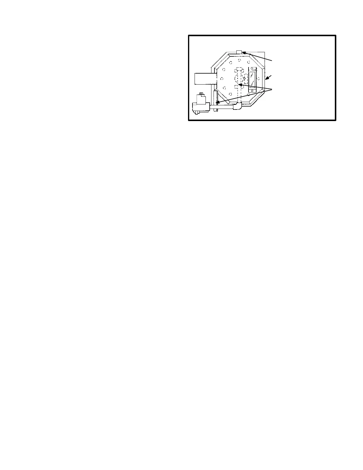
Figure 31 shows how to remove burner assembly.
1-Turn off power to unit and shut off gas supply.
2-Disconnect wires to rollout switch and gas valve.
3-Remove burner enclosure (if so equipped) by re
moving bolts securing enclosure to burner plate.
To remove the assembly, first remove octagon
backplate. Loosen nuts on top and bottom sur
faces at overlap and remove four mounting bolts
at burner plate.
4-Remove gas valve/manifold assembly by removing
bolts securing assembly to vestibule. Manifold,
valve and bracket will be removed as a unit.
NOTE - See figure 32 for CAUTION concerning
burner plate removal. First detach the gas man
ifold bracket. Next, remove the four screws secur
ing the gas burner manifold to the burner plate.
Take care not to damage ceramic cone in combus
tion chamber. If cone is damaged, it must be re
placed.
5-Slide burner off orifice.
6-Clean as necessary and reassemble (reverse
steps 1-5). Replace the four screws securing the
gas/burner manifold to the burner plate. (If burner
enclosure was previously removed, it must be
reassembled taking care not to create air leaks
due to misalignment of parts which will ad
versely affect unit performance.) Secure the
gas manifold bracket and ensure proper burner
head alignment. Bolts must be torqued to 35 in
lbs. to ensure proper operation.
7-Be sure to secure all wires and check plumbing and
burner plate for airtight seal.
8-Turn on power to unit. Follow lighting instructions
attached to unit and operate unit in heating mode.
Check burner flame. It should be blue with clear
yellow streaking.
FIGURE 31
GCS16 BURNER ASSEMBLY REMOVAL
1-Turn off power to unit.
2-Disconnect wires to rollout
switch and gas valve.
3-Remove burner enclosure
(if so equipped).
4-Remove valve/manifold
assembly.
5-Slide burner off orifice.
I-Burner Cone
When replacing the burner cone, the heat exchanger must
be removed. To remove or replace the burner cone refer
to the procedure for removing the heat exchanger in sec
tion K-Heat Exchanger."
CAUTION - AFTER UNIT HAS BEEN OPERATED,
BURNER CONE CAN BE EASILY DAMAGED BY
HANDLING. IT MUST BE HANDLED CAREFULLY.
CONE MUST BE REPLACED IF EITHER INSIDE OR
OUTSIDE EDGE ARE DAMAGED. A DAMAGED IN
SIDE EDGE CAN CAUSE IMPROPER OPERATION.
A DAMAGED OUTSIDE EDGE CAN CAUSE EX
HAUST PRODUCTS TO ENTER LIVING SPACE.
DO NOT ALLOW UNIT TO OPERATE WITH A DAM
AGED BURNER CONE.
J-Burner Plate Gasket
The burner plate gasket needs to be inspected or replaced
only when the burner plate or heat exchanger are re
moved. When replacing the burner plate gasket, the burn
er, gas valve and manifold assembly must be removed.
To Replace Burner Plate Gasket:
1-Turn off power to unit and shut off gas supply.
2-Disconnect rollout switch and gas valve wires.
3-Remove burner enclosure (if so equipped) by re
moving bolts securing enclosure to burner plate.
4-Remove gas valve/manifold assembly by removing
bolts securing assembly to vesibule.
5-Remove burner plate by removing bolts securing
burner plate to vestibule.
NOTE - See figure 32 regarding slots in burner plate.
 Loading...