Page 20
9-Flue Vent (Figure 15)
WARNING - VENT CAP ASSEMBLY MUST BE
INSTALLED WITHOUT MODIFICATION. ANY MOD
IFICATION TO THE VENT CAP ASSEMBLY OR
FAILURE TO INSTALL ASSEMBLY CAN RESULT
IN IMPROPER OPERATION AND WILL VOID THE
AGA/CGA CERTIFICATION OF THE UNIT.
CAUTION - DO NOT START OR OPERATE UNIT
UNLESS VENT CAP IS IN PLACE.
FIGURE 15
VENT
GASKET
VENT CAP
ASSEMBLY
TYPICAL FLUE VENT INSTALLATION
GCS16H-261/311 SHOWN
FOR ILLUSTRATION ONLY
NOT DRAWN TO SCALE
10-Burner Access Wind and Rain Shield
(Figure 16)
WARNING - THE BURNER ACCESS PANEL WIND
AND RAIN SHIELD MUST BE INSTALLED WITH
OUT MODIFICATION. IF EITHER THE BURNER AC
CESS PANEL OR WIND AND RAIN SHIELD IS NOT
INSTALLED OR IS MODIFIED, IMPROPER UNIT
OPERATION CAN RESULT AND AGA/CGA CER
TIFICATION OF UNIT WILL BE VOID.
BURNER ACCESS
PANEL
BURNER ACCESS
WIND SHIELD
SECURE WITH
FOUR SCREWS
(Provided)
UNIT
FIGURE 16
RAIN SHIELD
GCS16-410 THROUGH 650 SHOWN
TYPICAL BURNER ACCESS COVER
AND RAIN SHIELD
11-Combustion Air Blower Capacitor C3
All units equipped with 125K Btuh heat exchanger use a
singlephase PSC motor to power the combustion air
blower. A single run capacitor is mounted on the motor.
The capacitor is rated 4mfd at 370VAC.
All other heat exchanger sizes use a shaded pole motor to
power the combustion air blower. Shaded pole motors do
not require a run capacitor.
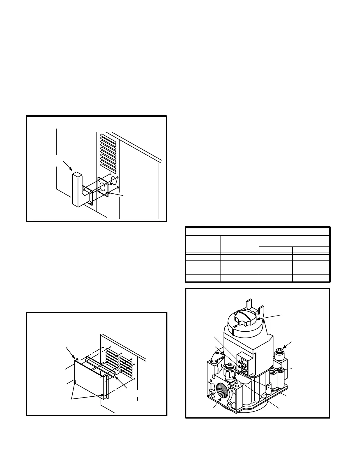
12-Gas Valve GV1
Gas valve GV1 is a singlestage redundant valve
manufactured by Honeywell. In 50,000 and 75,000 Btuh
heat exchangers, the valve is slow opening (1-10 sec
onds). 100,000 and 125,000 Btuh heat exchangers use
quick opening gas valves (1 sec. or less). On a call for
heat, the valve is energized by the ignition control simulta
neously with the spark electrode. When the valve is de
energized, it closes in 1/2 to 3 seconds. A manual shutoff
knob is provided on the valve for shutoff. Figure 17 shows
gas valve components. Table 5 shows factory gas valve
regulation for GCS16 series units.
TABLE 5
GAS VALVE REGULATION
Unit Input
K Btuh
Maximum
Inlet Pressure
in. W.C.
Operating Pressure
(outlet) in. W.C.
50
75
100
125
21.0
21.0
3.5 +0 -0.3
3.5 +0 -0.3
21.0 3.5 +0 -0.3
21.0 2.7 +0 -0.3
Natural L.P.
10.5
10.5
9.5
10.0
FIGURE 17
GAS VALVE GV1
INLET
PRESSURE
TAP
PRESSURE
REGULATOR
(under cap)
OUTLET
PRESSURE
TAP
W1
TERMINAL
C
TERMINAL
ON/OFF
KNOB
OUTLET
GROUND
TERMINALS
 Loading...