Page 53
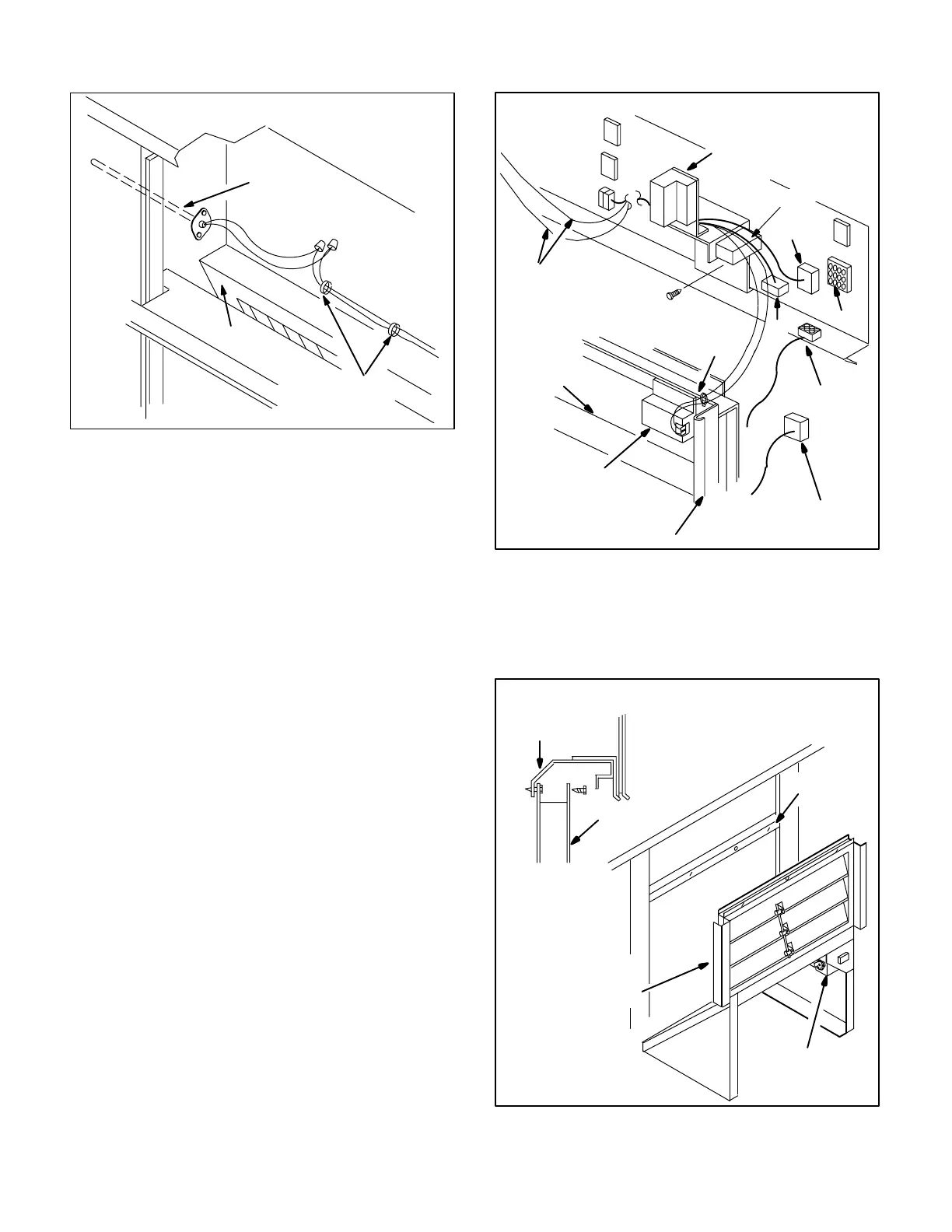
FIGURE 59
WIRE TIES
MIXED
AIR
SENSOR
REMD16
MIXED AIR SENSOR LOCATION
FILTER
e-Wiring, Installation, Maintenance
The economizer uses harness plugs to connect to the
unit harness connector located in the filter access
compartment. Unlike smaller 16 series economizers
which are unitary in construction (all one piece), the
REMD16M-185 economizer has a control relay kit
(consists of enthalpy control and relays) installed in
the unit filter access section. The damper section
(consists of dampers and damper motor) is installed
separately in the return air section. Figure 60 shows
economizer control installation and wiring. Figures
61 and 62 show REMD16M installation. Although
harness connectors are used to connect the to the
economizer, the economizer electrically connects to
the differently depending on which control system
has been installed. The different electrical connec
tions are made in relay kits and controls located in the
filter access area of the unit. All connections (except
for enthalpy sensor and mixed air sensor) are made
with quick-connect type harness connectors. For
specific details of economizer wiring and operation,
refer to the sequence of operation section of this
manual.
Figures 61 and 62 show how an REMD16M is
installed in a GCS16 cabinet (downflow application
shown). For detailed installation and maintenance in
structions, refer to the REMD16-185M installation in
structions.
DAMPERS
ENTHALPY
SENSOR
TO MIXED
AIR SENSOR
RELAY
ENTHALPY
CONTROL
REMD16M ENTHALPY CONTROL/RELAY KIT
FIGURE 60
P9
J3
P4
J9
REMD16M
P18
From PED16 used only
with power exhaust
WIRE TIE
REMD16M
f-Modulating Damper Motor Check
The following procedure checks only the damper mo
tor. For detailed economizer checkout procedure re
fer to Lennox' Solid State Economizer Checkout And
Troubleshooting Guide.
FIGURE 61
DAMPER
MOTOR
REMD16M
DAMPER
ASSEMBLY
REMD16M DAMPER ASSEMBLY INSTALLATION
HORIZONTAL
MULLION
HORIZONTAL
MULLION
DAMPER
FRAME
 Loading...
