Page 25
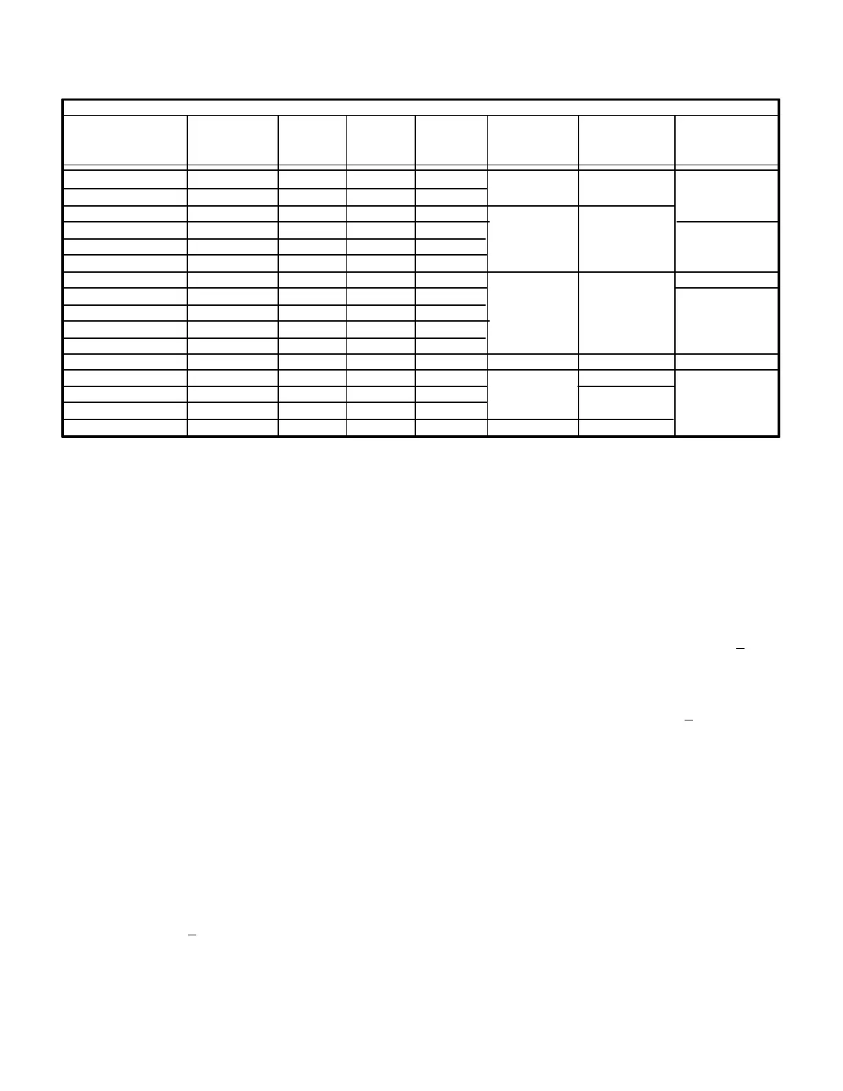
TABLE 6
Unit
Locked
Rotor
Amps
Rated
Load
Amps
Oil
Charge
Fl. Oz.
Oil TypeViscosity
Crankcase
Heater
Phase
GCS16 SERIES UNITS - COMPRESSOR SPECIFICATIONS
GCS16H-261
GCS16H-311
Voltage/
GCS16R-411
GCS16-411
GCS16-413
GCS16-413
208/230/1
208/230/1
208/230/1
208/230/1
460/3
GCS16R-511
GCS16-511
208/230/1
208/230/1
208/230/1
GCS16-513
GCS16-513
GCS16-513
208/230/3
460/3
575/3
GCS16R-651
GCS16-651
GCS16-653
GCS16-653
GCS16-653
208/230/1
208/230/1
208/230/3
460/3
575/3
57.0
77.5
83.5
83.5
66.0
35.0
118.0
118.0
90.0
45.0
36.0
135.0
135.0
105.0
55.0
45.0
40
40
55
55
55
55
55
55
55
55
50
70
70
70
70
70
190-210
190-210
190-210
**Heat Pump Grade Mineral
*Texaco Capella WF-32 or Suniso 3GS or White Oil M/M Sontex 200-LT
None
40 watt Insertion
Type Self
Regulating
None
30 watt Insertion
Type Self
Regulating
None
30 watt Insertion
Type Self
Regulating
*
Not Specified
**
**
**
12.0
13.5
17.6
17.6
11.5
5.3
23.5
23.5
15.4
8.4
6.4
27.6
27.6
17.6
9.4
8.4
1-Compressor B1
Table 6 shows the specifications of compressors used in
all units. Compressors used in GCS16 commercial units
are equipped with insertion type crankcase heaters. All
compressors are protected by internal pressure relief
valves and internal overload protection circuitry.
WARNING - COMPRESSOR MUST BE
GROUNDED. DO NOT OPERATE WITHOUT PRO
TECTIVE COVER OVER TERMINALS. DISCON
NECT POWER BEFORE REMOVING PROTECTIVE
COVER. DISCHARGE CAPACITORS BEFORE
SERVICING UNIT. FAILURE TO FOLLOW THESE
PRECAUTIONS COULD CAUSE ELECTRICAL
SHOCK RESULTING IN INJURY OR DEATH.
2-High Pressure Limit S4
The high pressure limit is a manually reset SPST N.C.
switch which opens on a pressure rise. All commercial
units (GCS16) are equipped with the limit. GCS16R and
GCS16H are not equipped with the limit. The switch is lo
cated in the compressor discharge line and is wired in se
ries with the compressor contactor. When discharge pres
sure rises above 410+10 psig (indicating a problem in the
system) the switch opens and the compressor is deener
gized ( the economizer can continue to operate.) After the
problem has been found and corrected, the switch can be
reset by pushingin the switch button.
3-Loss of Charge Switch S24
The loss of charge switch is an autoreset SPST N.C.
switch which opens on a pressure drop. All commercial
units (GCS16) are equipped with the switch. GCS16R and
GCS16H are not equipped with the switch. The switch is
located in the compressor discharge line and is wired in
series with the high pressure switch and compressor con
tactor. When discharge pressure drops below 25+5 psig
(indicating a loss of charge in the system) the switch
opens and the compressor is deenergized. The switch
automatically resets when refrigerant is added and pres
sure in the discharge line rises above 55+5 psig.
4-Start Capacitor C7
All singlephase units (size -511 and larger) use a com
pressor start capacitor (C7) connected in parallel with the
run capacitor (C5). The capacitor is energized during com
pressor startup and is switched off by potential relay K31
when the compressor nears full speed. Threephase units
do not use start capacitors. Table 7 shows start capacitor
ratings for singlephase GCS16s. The capacitor is
mounted in the unit control box. See figure 6 for capacitor
location.
The start capacitor uses a 15K ohm 2 watt bleed" resistor
connected in parallel with the capacitor terminals. The re
sistor is used to slowly discharge the capacitor when not in
use.

 Loading...