EasyManua.ls Logo

Lennox GCS16-953

Lennox GCS16-953
80 pages
To Next Page IconTo Next Page
Loading...
SERVICE
GCS16
UNIT
INFORMATION
6-25 TON UNITS
Page 1
1994 Lennox Industries Inc.
Corp. 9322-L3 Litho U.S.A.
GCS16 SERIES
GCS16 series units in the 6 ton and larger cooling size are
packaged combination two-stage gas heat / two-stage dx
cool units designed for commercial applications. Gas heat
sections are designed with Lennox' aluminized steel tube
heat exchangers ranging in size from 135,000 to 470,000
Btuh input. Units are designed for rooftop or side of building
installation with either bottom or horizontal discharge and
return air.
For commercial applications, the GCS16 is designed to ac
cept any of several different thermostat control systems with
minimum field wiring. Control options such as economizer,
warm up kit, Honeywell W973 control, Honeywell W7400
control or other field specified controls connect to the unit
with jack-plugs. When plugged in" the controls become an
integral part of the unit wiring. Units are also equipped with a
low voltage terminal strip to facilitate thermostat field wiring.
All specifications in this manual are subject to change.
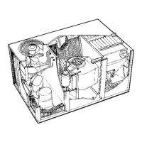
GCS16-1853 SHOWN
TABLE OF CONTENTS
Introduction Page 1. . . . . . . . . . . . . . . . . . . . . . . . . . . . . . . . . . . . . . .
Specifications Pages 2-9. . . . . . . . . . . . . . . . . . . . . . . . . . . . . . . . . .
Electrical Data Page 10. . . . . . . . . . . . . . . . . . . . . . . . . . . . . . . . . . .
Blower Data Pages 11-16. . . . . . . . . . . . . . . . . . . . . . . . . . . . . . . . . .
Air Resistance Data Pages 17-18. . . . . . . . . . . . . . . . . . . . . . . . . . .
Parts Arrangement Pages 18-22. . . . . . . . . . . . . . . . . . . . . . . . . . . .
I- APPLICATION Page 22. . . . . . . . . . . . . . . . . . . . . . . . . . . . . . . . . .
II- UNIT COMPONENTS Pages 22-41. . . . . . . . . . . . . . . . . . . . . . . . .
Control Box Components Pages 22-25. . . . . . . . . . . . . . . . . . . . . .
Heating Components Pages 26-34. . . . . . . . . . . . . . . . . . . . . . . . . .
Cooling Components Pages 34-40. . . . . . . . . . . . . . . . . . . . . . . . . .
Blower Compartment Components Pages 40-41. . . . . . . . . . . . . .
III- ELECTRICAL CONNECTIONS Page 41. . . . . . . . . . . . . . . . . . . .
IV- PLACEMENT AND INSTALLATION Page 41. . . . . . . . . . . . . . .
V- START UP - OPERATION Pages 41-42. . . . . . . . . . . . . . . . . . . . .
Preliminary Checks Page 41. . . . . . . . . . . . . . . . . . . . . . . . . . . . . .
Cooling / Heating Start Up Pages 41-42. . . . . . . . . . . . . . . . . . . . . .
Safety or Emergency Shut Down Page 42. . . . . . . . . . . . . . . . .
VI- COOLING SYSTEM CHECKS Page 42. . . . . . . . . . . . . . . . . . . . .
Gauge Manifold Attachment Page 42. . . . . . . . . . . . . . . . . . . . . . .
Charging Page 42. . . . . . . . . . . . . . . . . . . . . . . . . . . . . . . . . . . . . . . .
VII- HEATIING SYSTEM SERVICE CHECKS Pages 42-46. . . . . . . .
A.G.A./C.G.A. Applications and Requirements Page 42-43. . . . .
Gas Piping Page 43. . . . . . . . . . . . . . . . . . . . . . . . . . . . . . . . . . . . . .
Testing Gas Piping Page 43. . . . . . . . . . . . . . . . . . . . . . . . . . . . . . .
Testing Supply Pressure Page 43. . . . . . . . . . . . . . . . . . . . . . . . . .
Check and Adjust Manifold Pressure Page 43-44. . . . . . . . . . . . .
Proper Gas Flow Page 44. . . . . . . . . . . . . . . . . . . . . . . . . . . . . . . . .
High Altitude Derate Pages 44. . . . . . . . . . . . . . . . . . . . . . . . . . . . .
Inshot Burner Pages 44-45. . . . . . . . . . . . . . . . . . . . . . . . . . . . . . . . .
Heat Exchanger Page 45. . . . . . . . . . . . . . . . . . . . . . . . . . . . . . . . .
Ignition Control Page 45. . . . . . . . . . . . . . . . . . . . . . . . . . . . . . . . . .
Electrode Gap and Flame Sensing Pages 45-46. . . . . . . . . . . . .
Combustion Air Blower Page 46. . . . . . . . . . . . . . . . . . . . . . . . . . .
VIII- INDOOR BLOWER OPERATION / ADJUSTMENT
Pages 46-47. . . . . . . . . . . . . . . . . . . . . . . . . . . . . . . . . . . . . . . . . . . .
Blower Operation Page 46. . . . . . . . . . . . . . . . . . . . . . . . . . . . . . . .
Determining Unit CFM Page 46. . . . . . . . . . . . . . . . . . . . . . . . . . . .
Blower Belt Adjustment Pages 46-47. . . . . . . . . . . . . . . . . . . . . . .
IX- MAINTENANCE Page 47. . . . . . . . . . . . . . . . . . . . . . . . . . . . . . . . .
Filters Page 47. . . . . . . . . . . . . . . . . . . . . . . . . . . . . . . . . . . . . . . . . .
Lubrication Page 47. . . . . . . . . . . . . . . . . . . . . . . . . . . . . . . . . . . . .
Supply Air Blower Wheel Page 47. . . . . . . . . . . . . . . . . . . . . . . . . .
Evaporator and Condenser Coil Page 47. . . . . . . . . . . . . . . . . . . .
Electrical Page 47. . . . . . . . . . . . . . . . . . . . . . . . . . . . . . . . . . . . . . .
X- ACCESSORIES Pages 48-63. . . . . . . . . . . . . . . . . . . . . . . . . . . . .
RMF16 Roof Mounting Frame Page 48. . . . . . . . . . . . . . . . . . . . .
OAD16 Outdoor Air Damper Page 48. . . . . . . . . . . . . . . . . . . . . . .
Economizers Pages 48-54. . . . . . . . . . . . . . . . . . . . . . . . . . . . . . . .
Transitions and Supply / Return Diffusers Page 54. . . . . . . . . . . .
Firestats Page 54. . . . . . . . . . . . . . . . . . . . . . . . . . . . . . . . . . . . . . . .
Cycle Control Kit Page 55. . . . . . . . . . . . . . . . . . . . . . . . . . . . . . . . .
Low Ambient Kit Page 56. . . . . . . . . . . . . . . . . . . . . . . . . . . . . . . . .
Status Panels Pages 56-57. . . . . . . . . . . . . . . . . . . . . . . . . . . . . . .
Commercial Controls Hardware Pages 58-59. . . . . . . . . . . . . . . .
Optional Commecial Controls Systems Pages 59-63. . . . . . . . . .
Clocks / Timers Page 63. . . . . . . . . . . . . . . . . . . . . . . . . . . . . . . . . .
XI- WIRING DIAGRAMS / OPERATION SEQUENCE
Pages 64-79. . . . . . . . . . . . . . . . . . . . . . . . . . . . . . . . . . . . . . . . . . . .
Unit Operation Sequence Pages 64-75. . . . . . . . . . . . . . . . . . . . .
REMD16M Economizer Operation Sequence Pages 76-77. . . .
Warm Up Kit Operation Sequence Pages 78-79. . . . . . . . . . . . . .
Библиотека СОК
Question and Answer IconNeed help?

Do you have a question about the Lennox GCS16-953 and is the answer not in the manual?

Lennox GCS16-953 Specifications

General IconGeneral
BrandLennox
ModelGCS16-953
CategoryGas Heater
LanguageEnglish

Summary

Unit Information and Product Overview

GCS16 Series Product Introduction

Introduces GCS16 series as packaged two-stage gas/dx cool units for commercial applications.

GCS16 Series Specifications: Cooling Capacity and Blower Data

ARI Ratings and Refrigerant Charge

Details ARI ratings, refrigerant charge, and blower/drive specifications for GCS16 units.

GCS16 Series Specifications: Heating Capacity and Electrical Data

Two-Stage Heating Capacity and Gas Supply

Details two-stage heating capacity for natural and LPG gas, plus gas supply connections.

GCS16 Series Specifications: Larger Tonnage Models

GCS16-1853 Series Specifications Overview

Details specifications for GCS16-1853 series, including cooling capacity and heating input.

GCS16 Series Specifications: Higher Tonnage Models

GCS16-2553 Series Specifications Overview

Provides specifications for GCS16-2553 series, including cooling capacity and heating input.

GCS16 Series Specifications: GCS16-2753 Models

GCS16-2753 Series Specifications Overview

Lists specifications for GCS16-2753 series, including cooling capacity and heating input.

GCS16 Series Specifications: GCS16-3003 Models

GCS16-3003 Series Specifications Overview

Details specifications for GCS16-3003 series, including cooling capacity and heating input.

Optional Accessories

Optional Accessories for GCS16-823 and GCS16-953

Lists optional LPG conversion kits and roof mounting frames for specific GCS16 models.

Economizer Dampers and Exhaust Dampers for Larger Units

Details optional economizer and exhaust dampers, including filter sizes and face area.

Optional Accessories (Continued)

Optional Accessories for GCS16-1353 to GCS16-3003

Lists optional LPG conversion kits and roof mounting frames for GCS16-1353 to GCS16-3003.

Economizer Dampers and Exhaust Dampers for Larger Units

Details optional economizer and exhaust dampers for larger GCS16 units.

Electrical Data

Electrical Data for GCS16-823 to GCS16-1603 Series

Provides electrical data for compressors and condenser fan motors, including amps and horsepower.

Evaporator Blower Motor Specifications Overview

Details electrical data for the evaporator blower motor and minimum circuit ampacity.

Blower Performance

GCS16-823 and GCS16-953 Blower Performance Data

Presents blower performance data (RPM, BHP) at various air volumes and static pressures.

GCS16-1353 Blower Performance Data

Provides blower performance data for GCS16-1353 at different air volumes and static pressures.

Blower Performance (Continued)

GCS16-1603 and GCS16-1853 Blower Performance Data

Details blower performance for GCS16-1853-235, including RPM and BHP at various conditions.

Blower Speed Adjustment and Maintenance Procedures

Explains how to adjust blower speed and general maintenance for the blower compartment.

Blower Performance (Continued)

GCS16-1853-330 Blower Performance Data

Presents blower performance data for larger GCS16 models at various air volumes and static pressures.

Blower Performance (Continued)

GCS16-2553 & GCS16-2753 Blower Performance Data

Details blower performance for GCS16-2553 and GCS16-2753 units.

Blower Motor Specifications Overview

Lists specifications for blower motors, including HP, Usage, Volts, and Phase.

Blower Performance (Continued)

GCS16-2553-470 & GCS16-2753-470 Blower Performance Data

Provides blower performance data for higher tonnage GCS16 units.

Blower Motor Maintenance and Lubrication Requirements

Covers blower motor maintenance, including cleaning and lubrication requirements.

Blower Performance (Continued)

GCS16-3003 Blower Performance Data

Details blower performance for GCS16-3003 models at various operating conditions.

Accessory Air Resistance

Accessory Air Resistance Data for Economizers and Diffusers

Lists total resistance values for various economizer and diffuser accessories.

Power Exhaust Fans Performance

Power Exhaust Fans Performance Data and Ceiling Diffuser Air Throw

Provides air throw data for different ceiling diffuser types and air volumes.

GCS16-823953 Parts Arrangement Overview

Shows a diagram of the parts arrangement for GCS16-823/953 units.

Parts Arrangement

GCS16-13531603 Parts Arrangement Overview

Illustrates the parts arrangement for GCS16-1853 units, highlighting key components.

Parts Arrangement (Continued)

GCS16-255327533003 Parts Arrangement Overview

Identifies and illustrates the components within the control box for GCS16-823 and GCS16-953.

Control Box Components

Control Box Components for GCS16-1353, -1603 Series

Details the components found within the control box of the GCS16-1853 unit.

Unit Components

Control Box Components for GCS16-2553, -2753, -3003 Series

Explains the function and location of the power distribution terminal block (TB13).

Low Voltage Terminal Strip TB1 Usage

Describes the low voltage terminal strip (TB1) for thermostat and control wiring connections.

Unit Components (Continued)

Terminal Strip TB17 and Transformer T1 Functionality

Details terminal block TB17 and transformer T1, used for low voltage and control power.

Transformers T18, T3, and Fuses F10, F16 Explanation

Explains the function of transformers T18, T3, and fuses F10, F16 in the control system.

Control Box Components (Continued)

Compressor Contactors K2, K14 and Blower Contactor K3

Describes the function of condenser fan contactors K10 and K68 in controlling fan operation.

Combustion Air Blower Relay K13 and Pilot Relay Board A11

Details the combustion air blower relay K13 and pilot relay board A11 functions.

Control Box Components (Continued)

Compressor Motor Protectors A9, A10 and Low Ambient Lockout S3

Explains the function of low ambient lockout switch S30 and compressor delay DL15.

Low Ambient Lockout Switch S30 and Compressor Delay DL15 Function

Explains the function of low ambient lockout switch S30 and compressor delay DL15.

Heat Exchanger Assembly

Typical Heat Exchanger Assembly Configurations

Illustrates typical heat exchanger assemblies, showing single and dual configurations.

Heating Control Components

Heating Control Components for GCS16-823 to -1603 Series

Shows heating control components for units with a single heat exchanger.

Heating Controls for Dual Heat Exchanger Units

Illustrates heating control components for units equipped with dual heat exchangers.

Heating Control Box Components

Transformer and Relay Functions in Heating Controls

Explains the roles of K13 (combustion air blower) and K20 (indoor blower limit) relays.

2 nd Stage Heat Relay K19 and Heat Blower Relays K56, K57

Details the function of K19 (2nd stage heat) and K56/K57 (heat blower) relays.

Ignition (Burner) Control

Ignition Control A3 Operation and Safety Warnings

Details the ignition control A3 function and essential safety warnings.

Spark ElectrodeFlame Sensor Gap and Flame Sensing

Explains the importance of proper spark electrode and flame sensor gap for ignition.

Burner Removal and ElectrodeSensor Orientation Guide

Provides instructions for burner removal and electrode/sensor orientation.

Ignition Control Operation

Normal Ignition Sequence, Retrials, and Timing

Explains the timing sequences for the Fenwal ignition control, including retrials and lockout.

Heat Exchanger Function and Gas Valve Staging

Details the function of heat exchangers and how the gas valve stages heating operation.

Burner Assembly

Burner Assembly Components and Gas Valve Operation

Describes the burner assembly, orifices, and their function in gas flow.

Primary and Secondary High Temperature Limit Switches

Explains the function of primary (S10) and secondary (S21) high temperature limit switches.

Safety Limits and Controls

Flame Rollout Switches S47 and S69 Functionality

Details the function of flame rollout switches S47 and S69 for safety during heating.

Combustion Air Blower B6, B15 and Prove Switches S18, S45

Explains the combustion air blower operation and the role of prove switches S18 and S45.

Gas Valve and Electrode Assembly

Gas Valve (GV1, GV3) Components and Regulation Details

Details gas valve operation, regulation, and factory settings for GCS16 units.

Electrode Assembly for Ignition and Flame Sensing

Describes the electrode assembly used for ignition spark and flame sensing.

Ignition Sequence and Cooling Components

Ignition Sequence and Spark Electrode Functionality

Explains the function of the spark electrode and flame sensor in the ignition process.

GCS16-823,-953 Plumbing Components Overview

Shows a diagram of the plumbing components for GCS16-823 and GCS16-953 units.

Plumbing Components

GCS16-1353,-1603 Compressor Compartment Plumbing

Illustrates the plumbing components in the condensing section for GCS16-1853 units.

Plumbing Components (Continued)

GCS16-1853 Plumbing - Condensing Section Liquid Lines

Shows plumbing components for the condensing section of GCS16-2553, -2753, -3003.

Evaporator Plumbing

Evaporator Plumbing for GCS16-823,-953,-1353,-1603 Series

Illustrates the evaporator section plumbing for GCS16-1853 units.

Compressors and Warnings

Compressor Overview and Safety Precautions for GCS16 Units

Discusses compressor operation, crankcase heaters, and essential safety warnings.

Compressor Components and Safety Limits

Crankcase Heaters and High Pressure Limit Switch Functions

Details the function of high pressure limit switches in protecting compressors.

Loss of Charge Switches and Thermometer Well Usage

Explains loss of charge switches and the use of thermometer wells for charging.

Condenser Fans and Blower Compartment

Condenser Fans B4 and B5 Specifications and Operation

Details the indoor blower motor specifications and components within the blower compartment.

Electrical Connections

Line Voltage Terminal Strips TB2 and TB1 for Wiring

Provides guidance on unit placement, installation, and ensuring compliance with codes.

Cooling Startup Procedures and Important Warnings

Outlines cooling startup procedures, including essential warnings about compressor heaters.

Startup - Operation

Heating Startup Procedures and Safety Warnings

Details cooling system checks, focusing on the approach method for refrigerant charge.

Gauge Manifold Attachment and Refrigerant Charging

Explains how to attach gauge manifolds and perform refrigerant charging.

Heating System Service Checks

Gas Piping Requirements and Pressure Testing Procedures

Describes gas piping components and safety precautions for installation and testing.

Testing Gas Supply and Manifold Pressures

Details procedures for testing gas supply and manifold pressures.

Gas Supply and High Altitude Considerations

Manifold Pressure Specifications and Gas Flow Checks

Explains how to check gas flow and adjust for high altitude derating.

Inshot Burner Description and Flame Viewing Guide

Describes the inshot burner and how to view the flame for proper operation.

Burner and Heat Exchanger Access

Burner Flame Checks and Heat Exchanger Access Procedures

Details the ignition control A3 function and essential safety warnings.

Spark ElectrodeFlame Sensor Gap and Flame Sensing

Explains the correct gap for spark electrodes and the flame sensing process.

Indoor Blower Operation Adjustment

Blower Operation and Determining Unit CFM

Explains how to measure unit CFM using static pressure and blower RPM.

Blower Belt Adjustment Procedures

Details the procedure for adjusting the blower belt tension and alignment.

Maintenance

Filter Maintenance and Lubrication Requirements

Provides instructions for cleaning evaporator and condenser coils for optimal performance.

Evaporator and Condenser Coil Cleaning Procedures

Covers electrical checks, including wiring and motor ratings verification.

Electrical Checks and Motor Ratings Verification

Covers electrical checks, including wiring and motor ratings verification.

Accessories

RMF16 Mounting Frame Installation Guidelines

Details the installation procedure for the OAD16 outdoor air damper section.

OAD16 Outdoor Air Damper Installation Procedure

Details the installation procedure for the OAD16 outdoor air damper section.

Economizer Components and Optional Accessories

Describes economizer components like dampers, sensors, and optional accessories.

Accessories (Continued)

REMD16 M Downflow Economizer Installation Guide

Explains the operation and control of the REMD16M economizer.

REMD16 M Economizer Operation and Controls Explanation

Explains the operation and control of the REMD16M economizer.

Accessories (Continued)

EMDH16 M Horizontal Economizer and PED16 Exhaust Damper

Provides performance data for the PED16 power exhaust damper.

PED16 Power Exhaust Damper Performance Data

Provides performance data for the PED16 power exhaust damper.

Economizer Accessories: GED16 Gravity Exhaust Dampers

Details optional GED16 gravity exhaust dampers for economizer systems.

Accessories (Continued)

PED16 Control Kit and Enthalpy Control Installation

Describes the warm-up kit for economizers, including installation and function.

Warm Up Kit for Economizer Systems Functionality

Describes the warm-up kit for economizers, including installation and function.

Economizer Operation and Controls: Setpoint Control Function

Explains the setpoint control function of the economizer's enthalpy control.

Economizer Control Adjustments

Economizer Setpoint Adjustment and Minimum Positioner

Details the function of the enthalpy and mixed air sensors in economizer operation.

Enthalpy Sensor and Mixed Air Sensor Functionality

Details the function of the enthalpy and mixed air sensors in economizer operation.

Economizer Installation and Check

REMD16 M Economizer Wiring and Installation Guide

Outlines the procedure for checking the modulating damper motor on REMD16M economizers.

Modulating Damper Motor Check Procedure

Outlines the procedure for checking the modulating damper motor on REMD16M economizers.

Economizer Operation and Controls

Economizer Operation Sequence and Minimum Position Adjustment

Describes optional transitions and supply/return diffusers for economizer systems.

Transitions and Diffuser Options for Economizers

Describes optional transitions and supply/return diffusers for economizer systems.

Firestats Installation Requirements and Function

Explains the requirements for installing firestats according to local codes.

Cycle Control Kit

Cycle Control Kit Wiring Diagram and Overall Function

Details the function of the cycle control kit, including delays for compressor and blower operation.

Low Ambient Kit

Low Ambient Kit Installation and Operation Guidelines

Explains how compressor monitors interact with low ambient kits and wiring considerations.

Compressor Monitor and Low Ambient Kit Wiring Considerations

Explains how compressor monitors interact with low ambient kits and wiring considerations.

Status Panels SP11 and SSP11 Overview

Introduces status panels SP11 and SSP11 for monitoring system operation.

Status Panels

SP11 Application and Panel Functions

Describes the application and functions of the SSP11 switching status panel.

SSP11 Application and Panel Functionality

Describes the application and functions of the SSP11 switching status panel.

SSP11 Indicators and System Controls Explanation

Explains the indicators and control functions of the SSP11 panel.

Commercial Controls Hardware

Jackplugs and Connectors for Commercial Controls Systems

Details the function of Jack J2/P2 and J3/P3 for heating and economizer connections.

Jack J2 P2 and J3 P3 Connection Functions

Details the function of Jack J2/P2 and J3/P3 for heating and economizer connections.

Jack J16 P16 and J18 P18 Connection Usage

Explains the use of J16/P16 for control systems and J18/P18 for power exhaust dampers.

Commercial Controls Systems

Jack J24 J25 J33 and J36 P36 Connection Details

Describes the J57 connection for the optional "dirty filter" indicator switch.

Jack J57 Filter Switch Connection Functionality

Describes the J57 connection for the optional "dirty filter" indicator switch.

Optional Commercial Controls Systems Overview

Lists optional commercial control systems and their associated wiring diagrams.

Optional Thermostat Control Systems

Warm-Up Kit Installation for Economizer Systems

Shows the relay kit installation for warm-up kits on smaller GCS16 units.

Warm-Up Kit Relay Installation for 12.5 Ton and Smaller Units

Shows the relay kit installation for warm-up kits on smaller GCS16 units.

Warm-Up Kit Relay Installation for 15 Ton and Larger Units

Illustrates the relay kit installation for warm-up kits on larger GCS16 units.

Wiring Diagrams for Control Systems

C1 Wiring Diagram and System Compatibility Warnings

Details the C2-1 wiring diagram for systems with economizers and warm-up kits.

C2-1 Wiring Diagram for Economizer and Warm-Up Systems

Details the C2-1 wiring diagram for systems with economizers and warm-up kits.

C11-1 Wiring Diagram and Night Setback Functionality

Explains the C11-1 wiring diagram and how it facilitates night setback.

Control System Wiring Diagrams

C3 and C4 Wiring Diagrams for Flexstat Controls

Details the C5 and C6 wiring diagrams for Prostat control systems.

C5 and C6 Wiring Diagrams for Prostat Controls

Details the C5 and C6 wiring diagrams for Prostat control systems.

C7-3 Wiring Diagram for W7400 Control System

Describes the C7-3 wiring diagram for the Honeywell W7400 control system.

Control System Wiring Diagrams (Continued)

C8-1 and C14-1 Wiring Diagrams for W973 Control System

Explains the C12 wiring diagrams for T7300 electronic thermostats.

C12 Wiring Diagrams for T7300 Thermostats

Explains the C12 wiring diagrams for T7300 electronic thermostats.

Clocks Timers (CMC3-1) and Wiring Connections

Details the CMC3-1 time clock and its wiring connections for setback operation.

Wiring Diagrams and Operating Sequence

C1 Diagram with B1 Diagram - Electromechanical Thermostat

Describes the step-by-step operation sequence for GCS16-823/953 with an electromechanical thermostat.

Operating Sequence

Electromechanical Thermostat Operation Sequence for GCS16-823953

Details the sequence of operations for cooling demand in GCS16-823/953 units.

Cooling Demand Sequence for GCS16-823953 Units

Details the sequence of operations for cooling demand in GCS16-823/953 units.

Heating Demand Sequence for GCS16-823953 Units

Outlines the sequence of operations for heating demand in GCS16-823/953 units.

Wiring Diagrams (Continued)

B2 Diagram with C1 Diagram for GCS16-1353 Models

Describes the operation sequence for GCS16-1353 units with an electromechanical thermostat.

Operating Sequence (Continued)

Electromechanical Thermostat Operation Sequence for GCS16-1353

Details the sequence of operations for cooling demand in GCS16-1353 units.

Cooling Demand Sequence for GCS16-1353 Units

Details the sequence of operations for cooling demand in GCS16-1353 units.

Heating Demand Sequence for GCS16-1353 Units

Outlines the sequence of operations for heating demand in GCS16-1353 units.

Wiring Diagrams (Continued)

B2 Diagram with C1 Diagram for GCS16-1603 Models

Describes the operation sequence for GCS16-1603 units with an electromechanical thermostat.

Operating Sequence (Continued)

Electromechanical Thermostat Operation Sequence for GCS16-1603

Details the sequence of operations for cooling demand in GCS16-1603 units.

Cooling Demand Sequence for GCS16-1603 Units

Details the sequence of operations for cooling demand in GCS16-1603 units.

Heating Demand Sequence for GCS16-1603 Units

Outlines the sequence of operations for heating demand in GCS16-1603 units.

Wiring Diagrams (Continued)

B9 and A8 Diagrams with C1 Diagram for GCS16-1853 Models

Describes the operation sequence for GCS16-1853 units with an electromechanical thermostat.

Operating Sequence (Continued)

Cooling Demand Sequence for GCS16-1853 Units

Details the sequence of operations for heating demand in GCS16-1853 units.

Heating Demand Sequence for GCS16-1853 Units

Details the sequence of operations for heating demand in GCS16-1853 units.

Wiring Diagrams (Continued)

B41 and A9 Diagrams with C1 Diagram for GCS16-2553 to -3003

Describes the operation sequence for GCS16-2553/2753/3003 units with electromechanical thermostat.

Operating Sequence (Continued)

Cooling Demand Sequence for GCS16-255327533003 (470,000 BTUH)

Details the heating demand sequence for higher BTUH GCS16 models.

Heating Demand Sequence for GCS16-255327533003 (470,000 BTUH)

Details the heating demand sequence for higher BTUH GCS16 models.

Wiring Diagrams (Continued)

C1 Diagram with B41 and A8 Diagrams for GCS16-2553 to -3003

Describes the operation sequence for GCS16-2553/2753/3003 units with electromechanical thermostat.

Operating Sequence (Continued)

Cooling Demand Sequence for GCS16-255327533003 (470,000 BTUH)

Details the heating demand sequence for higher BTUH GCS16 models.

Heating Demand Sequence for GCS16-255327533003 (470,000 BTUH)

Details the heating demand sequence for higher BTUH GCS16 models.

Wiring Diagrams (Continued)

C1 Diagram with D5 Diagram - Electromechanical Thermostat with Economizer

Shows wiring connections for economizer components like enthalpy control and damper motors.

Economizer Components and Wiring Connections

Shows wiring connections for economizer components like enthalpy control and damper motors.

Economizer Operation with Thermostat

REMD16 M Economizer Operation with Electromechanical Thermostat

Explains economizer operation during low and high enthalpy conditions for cooling.

Enthalpy Low and High Stage Cooling Operation Modes

Explains economizer operation during low and high enthalpy conditions for cooling.

Night Setback Operation and Warm-Up Kit Functionality

Details night setback operation and the function of the warm-up kit with economizers.

Wiring Diagrams (Continued)

C2-1 Diagram with D5 Diagram - Thermostat, Economizer, and Warm-Up

Shows wiring connections for economizer and warm-up kits with thermostats.

Economizer and Warm-Up Kit Wiring Connections

Shows wiring connections for economizer and warm-up kits with thermostats.

Warm-Up Kit Operation

Warm-Up Kit Operation Sequence with Economizer

Explains how the warm-up kit functions during night setback and morning warm-up.

Night Setback and Warm-Up Kit Functionality Details

Explains how the warm-up kit functions during night setback and morning warm-up.

Notes

Related product manuals