Page 62
6- C3 Wiring Diagram
Flexstat L2F-N for units without economizer or warm-
up. Setback is built in. Wiring connections are made
to the unit's low voltage terminal strip.
NOTE - Flexstat (C3 and C4 diagrams) was discontin
ued as a control system option in July 1989 and is not
shown in the GCS16-1853. However, Flexstat remains
a valid matchup to commercial GCS16 units of all sizes
until inventories are depleted. You may find some
GCS16-1853 units using it.
7- C4 Wiring Diagram
Flexstat L2F-N for units with economizer and warm-
up. Setback is built in. Thermostat wiring connections
are made to the unit's low voltage terminal strip while
the warm up kit plugsin" to the unit's control har
ness.
8- C5 Wiring Diagram
Prostat T5010 for units without economizer or warm-
up. Setback is built in. Wiring connections are made
to the unit's low voltage terminal strip.
9- C6 Wiring Diagram
Prostat T5010 for units with economizer and warm-
up. Setback is built in.Thermostat wiring connections
are made to the unit's low voltage terminal strip while
the warm up kit plugsin" to the unit's control harness
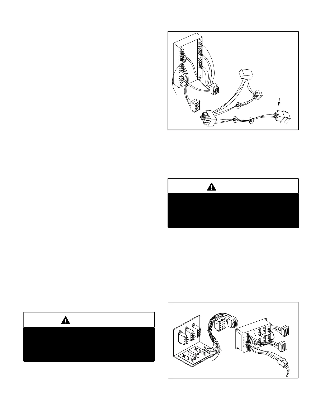
10- C7-3 Wiring Diagram
W7400 control system for units. See figure 75. Re
quires W7400 relay kit and economizer. Warm up and
setback are built in. Thermostat T7400 wiring con
nections are made to the unit's low voltage terminal
strip. W7400 control module jackplugs J17/P17
connect to the unit control harness at jackplug
J16/P16. W7400 relay kit plug P5 connects to unit
jack J3 and relay kit jack J5 connects to warm up kit
plug P8. Another plug equipped in the W7400 relay
kit, Jackplug J23/P23, is used in LVAV applications
only.
WARNING
Connect only relay kits designed for this control
system. Relay kits designed for other control sys
tems are not compatible and control damage or
failure will result. For example, do not connect a
W973 relay kit to this control system.
The W7400 is used only with the C73 control system
option. It cannot be used with any other control sys
tem option or control damage will result.
FIGURE 75
W7400
CONTROL SYSTEM
Control Module
Relay Kit
J17
P17
J5
P5
J23/P23
LVAV
APPLICATION
ONLY
The Honeywell W7400/T7400 control system, when
applied to the GCS16, allows fully programmable op
eration of the unit during occupied and unoccupied pe
riods. Morning warm-up capabilities are built in to the
control system. An external warm-up kit is not needed.
CAUTION
Do not connect a warmup kit to jack J5 of the
W7400 relay kit. Warm-up kit wiring is not compat
ible with W7400 wiring and component damage
will result. The W7400 system has a warm-up fea
ture built in. A warm-up kit is not needed.
11- C8-1 Wiring Diagram
W973 control system for units without economizer or
warm-up. See figure 76. Requires W973 relay kit and
CMC3-1 clock for night setback. W973 control module
jackplugs J17/P17 connect to the unit control har
ness at jackplug J16/P16. W973 relay kit plug P6 con
nects to unit jack J3 and relay kit jack J6 connects to
unit plug P3 or economizer plug P4. Room tempera
ture sensor connections are made to the unit's low
voltage terminal strip.
FIGURE76
W973 THERMOSTAT CONTROL KIT
Control Module
Relay Kit
J17
P19/J19
P17
P6
J6
 Loading...
