Page 28
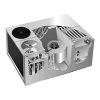
FIGURE 27
EVAPORATOR PLUMBING
GCS16-511/513, GCS16-651/653
GCS16R-511 and GCS16R-651
EVAPORATOR
EXPANSION
VALVE FED BY
LIQUID LINE
SUCTION
LINE
SENSING
BULB STRAPPED
TO SUCTION LINE
FEEDER TUBES
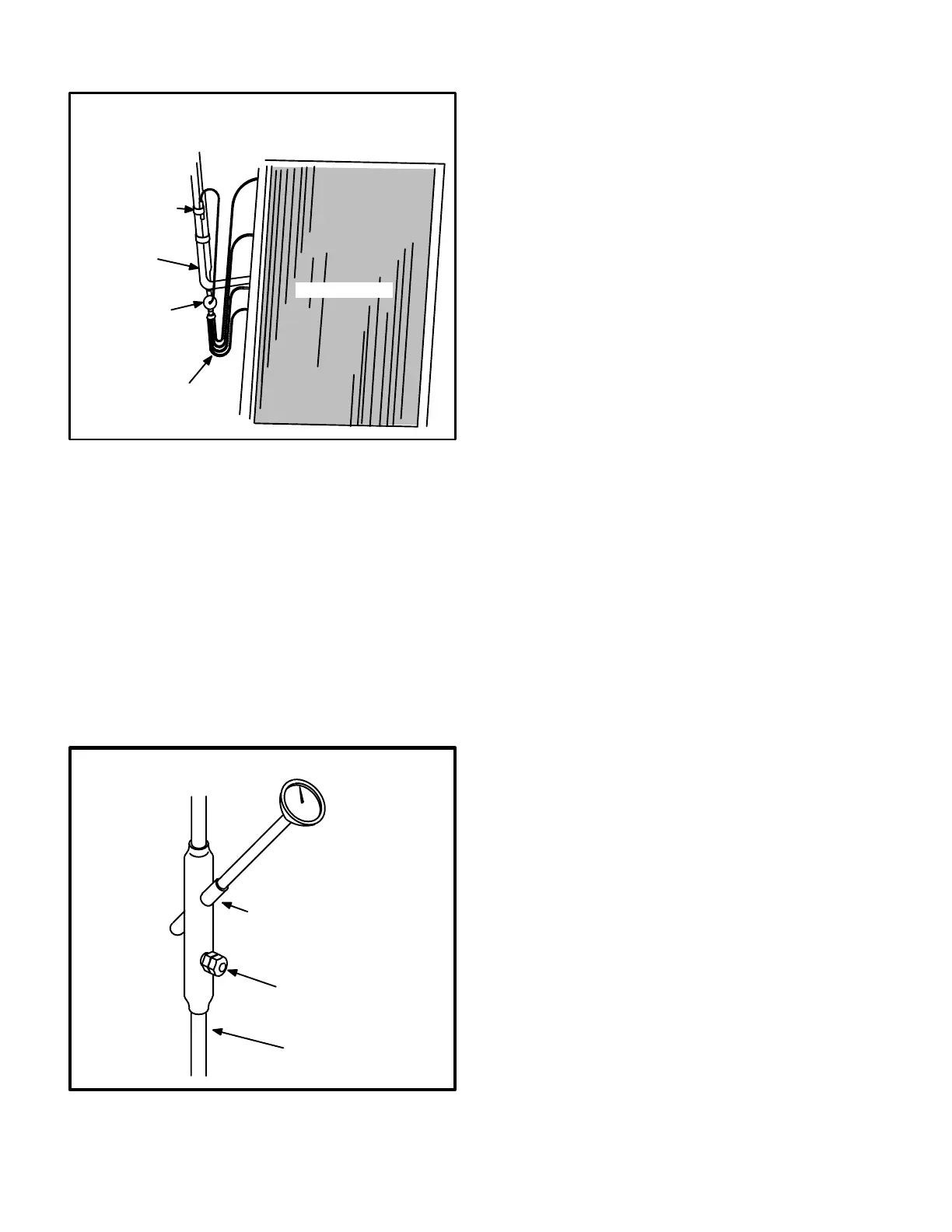
12-Thermometer Well (Figure 28)
All units are factory equipped with a thermometer well for
charging the unit. The well is used to accurately measure
the temperature of the liquid line. The temperature mea
sured is then used to calculate the approach or subcooling
temperature. Approach and subcooling temperatures are
compared to tables printed in the charging section of this
manual to determine the correct charge. The thermome
ter wells are equipped with a gauge port for connection of
high pressure gauge.
To accurately measure the temperature of the liquid line,
the well should be filled with a light mineral oil before using.
This will ensure good heat transfer to the thermometer.
FIGURE 28
THERMOMETER WELL
THERMOMETER WELL
LIQUID LINE
GAUGE PORT
LIQUID LINE
III-PLACEMENT AND INSTALLATION
Make sure that the unit is installed in accordance with the
installation instructions and all applicable codes. See ac
cessories section for conditions requiring use of the op
tional roof mounting frame (RMF16).
IV-ELECTRICAL CONNECTIONS
A-Power Supply
Refer to startup directions and refer closely to the unit wir
ing diagram when servicing. Refer to unit nameplate for
minimum circuit ampacity and maximum fuse size.
208/460/575 volt units are factory wired with red wire con
nected to control transformer primary. 230 volt units are
field wired with orange wire connected to control trans
former primary.
DANGER - ALL SINGLEPHASE UNITS USE
SINGLEPOLE CONTACTORS. COMPRESSOR
(TERMINAL R), ONE LEG OF THE START AND
RUN CAPACITORS AND ONE LEG OF THE CON
DENSER FAN ARE POWERED AT ALL TIMES.
MAKE SURE POWER IS TURNED OFF AT DISCON
NECT BEFORE SERVICING UNIT.
V-STARTUP - OPERATION
A-Preliminary Checks
1- Make sure that the unit is installed in accordance with
the installation instructions and applicable codes.
2- Inspect all electrical wiring, both field and factory
installed for loose connections. Tighten as required.
3- Check to ensure that refrigerant lines are in good con
dition and do not rub against the cabinet or other re
frigerant lines.
4- Check voltage at the disconnect switch. Voltage must
be within the range listed on the nameplate. If not,
consult the power company and have the voltage con
dition corrected before starting the unit.
5- Recheck voltage with unit running. If power is not with
in range listed on unit nameplate, stop unit and consult
power company. Check amperage of unit. Refer to
unit nameplate for correct running amps.

 Loading...