Page 31
VII-HEATING SYSTEM SERVICE CHECKS
A-A.G.A./C.G.A. Applications and Require
ments
All GCS16s are A.G.A and C.G.A. design certified without
modification.
Refer to the GCS16 Operation and Installation Instruction
Manual for more information.
B-Gas Piping
Gas supply piping must not allow more than 0.5"W.C. drop
in pressure between the gas meter and the unit. Supply
gas pipe must not be smaller than the unit gas connection.
Compounds used on threaded joints of gas piping should
be resistant to the action of liquefied petroleum gas.
C-Testing Gas Piping Pressure
NOTE - In case emergency shutdown is required, turn
off the main manual shutoff valve and disconnect the
main power to the unit. These controls should be prop
erly labeled by the installer.
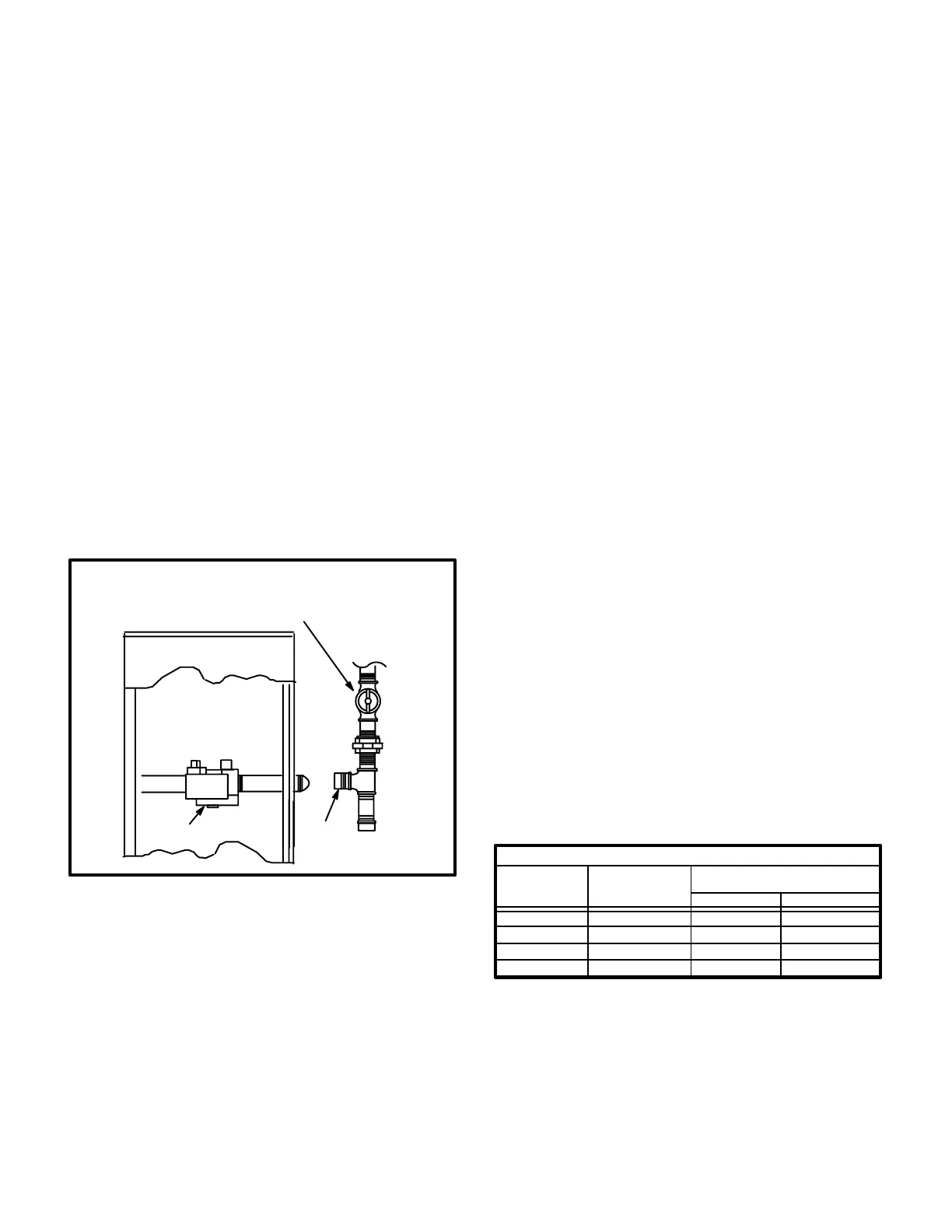
FIGURE 29
GAS VALVE
CAP
MANUAL MAIN SHUT-OFF VALVE
WILL NOT HOLD TEST PRESSURES
IN EXCESS OF 0.5 PSIG (14"w.c.)
UNIT
When pressure testing gas lines, the gas valve must be
disconnected and isolated. Gas valves can be damaged if
subjected to more than 0.5 psig (14"W.C.). See Figure 29.
If the test pressure is equal to or less than 0.5 psig
(14"W.C.), use the main manual shutoff valve before
pressure testing to isolate the unit from the gas supply sys
tem.
When checking piping connection for gas leaks, use a
soap solution or other preferred means. Do not use
matches, candles, flame, or other source of ignition to
check for gas leaks.
D-Testing Gas Supply Pressure
When testing gas supply pressure, connect test gauge to
the inlet pressure tap (field provided). Test supply gas
pressure with unit firing at maximum rate. Make sure the
reading falls within the range of the following values. Low
pressure may result in erratic operation or underfire."
High pressure can result in permanent damage to the gas
valve or overfire." For natural gas units, operating pres
sure at the unit gas connection must be between 4.5"W.C.
and 13.5"W.C. For L.P. gas units, operating pressure at
the unit gas connection must be between 11"W.C. and
13.5"W.C.
On multiple unit installations, each unit should be checked
separately, with and without the other units operating.
Supply pressure must fall within the range listed in the pre
vious paragraph.
E-Check and Adjust Manifold Pressure
After line pressure has been checked and adjusted, check
manifold pressure. Refer to figure 30 for location of man
ifold pressure adjustment screw. See figure 17 for location
of pressure tap on the gas valve.
The gas valve is factory set and should not require adjust
ment. All gas valves are factory regulated as shown in
table 14. The gas valve should completely and immediate
ly cycle off in the event of gas or power failure. The manual
shutoff knob can be used to immediately shut off gas sup
ply.
TABLE 14
MANIFOLD PRESSURE
Unit Input
K Btuh
Maximum
Inlet Pressure
in. W.C.
Operating Pressure
(outlet) in. W.C.
50
75
100
125
21.0
21.0
3.5 +0 -0.3
3.5 +0 -0.3
21.0 3.5 +0 -0.3
21.0 2.7 +0 -0.3
Natural L.P.
10.5
10.5
9.5
10.0
CAUTION-For safety, connect a shutoff valve be
tween the manometer and the gas tap to permit
shut off of gas pressure to the manometer.

 Loading...