Page 38
D-Blower Speed Adjustment
460V and 575V Units ONLY
All 460V and 575V units have three speed blower motors
with pigtail leads (taps). The taps are arranged as shown
in table 20. Both 460V and 575V units use 460V blower
motors. 575V units use a stepdown transformer in the
unit control box to provide 460V to the motor.
TABLE 20
FOUR SPEED BLOWER MOTORS
Speed Tap Color
Low
Medium
High
Internal Circuit
Common
Red
Yellow
Black
Blue
Orange
The motor is equipped with speed leads (taps) for chang
ing motor speed. The taps are connected to harness plug
P38 along with line voltage wires from blower relay. Jump
er J38 is used to complete the circuit to the blower motor
and provide the proper heating and cooling speed. J38 is
also used to provide the necessary blue leg" circuit which
460V motors require (refer to figure 24 for more informa
tion). Blower speed selection is accomplished by chang
ing the harness jumpers in the harness connector at the
blower motor (see figure 38).
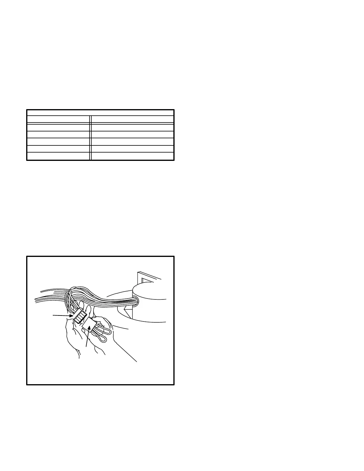
FIGURE 38
BLOWER SPEED TAP SELEC
TION
460V and 575V UNITS
P38
J38
Three J38 jumpers are provided with the unit. Each is marked
with different speeds. To change blower speeds, disconnect the
installed J38 jumper and install one of the other J38 jumpers.
BLOWER
BLOWER
MOTOR
Three J38 jumpers are provided with the unit. Each pro
vides the speeds marked on the jack (HiCool / LoHeat,
MedCool / MedHeat or HiCool / MedHeat) and the
blue leg" circuit referred to in figure 24.
Use the steps outlined in the previous section (Blower
Speed Adjustment 208V/230V Only) to determine which
J38 jumper to use.
WARNING - DO NOT ISOLATE MEDIUM OR LOW
SPEED WINDINGS WHEN OPERATING AT ME
DIUM OR LOW SPEED. THE BLUE LEAD MUST
NEVER BE CONNECTED TO A POWER LEAD
(BLOWER DEMAND FROM HEAT RELAY OR
BLOWER RELAY) OR TO COMMON. FAILURE TO
CONNECT THE BLUE TAP AS SHOWN ON THE
UNIT DIAGRAM WILL CAUSE IMPROPER OPERA
TION, INCREASED CURRENT FLOW AND/OR
BURNT WINDINGS.
IX-MAINTENANCE
CAUTION - TURN OFF GAS AND ELECTRICAL
POWER TO THE UNIT BEFORE PERFORMING
ANY MAINTENANCE OR SERVICE OPERATION
ON THE UNIT. REMEMBER TO FOLLOW LIGHT
ING INSTRUCTIONS ATTACHED TO THE UNIT
WHEN PUTTING THE UNIT BACK INTO OPERA
TION.
BE CAREFUL WHEN SERVICING UNIT TO AVOID
ACCIDENTAL CONTACT WITH SHARP METALLIC
EDGES WHICH MAY CAUSE INJURY.
A-Lubrication
NOTE - Always relubricate motors according to
manufacturer's lubrication instructions provided on
each motor. If no instructions are provided, use the fol
lowing as a guide:
1- Supply Air Motor Bearings - Bearings are prelubri
cated; no further lubrication is required for 10
years of normal operation. Thereafter, oil at oiling
ports or clean and repack bearings with a suitable
bearing grease every two years, whichever is ap
plicable.
2- Combustion Air Blower Motor Bearings - Bearings
are prelubricated. For extended bearing life, lubri
cate each bearing through the oiling ports pro
vided. Use a few drops of a good grade of electric
motor oil or SAE10 or SAE20 nondetergent motor
oil every two years.
3- Condenser Fan Motor Bearings - Bearings are
prelubricated. For extended bearing life, lubricate
each bearing through the oiling ports provided with
a few drops of a good grade electric motor oil or
SAE10 or SAE20 nondetergent motor oil every
two years.

 Loading...