Page 48
compartment. All connections are made with quick
connect type harness connectors. For specific de
tails of economizer wiring and operation, refer to the
sequence of operation section of this manual.
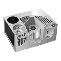
Figure 51 shows how an REMD16 is installed in a
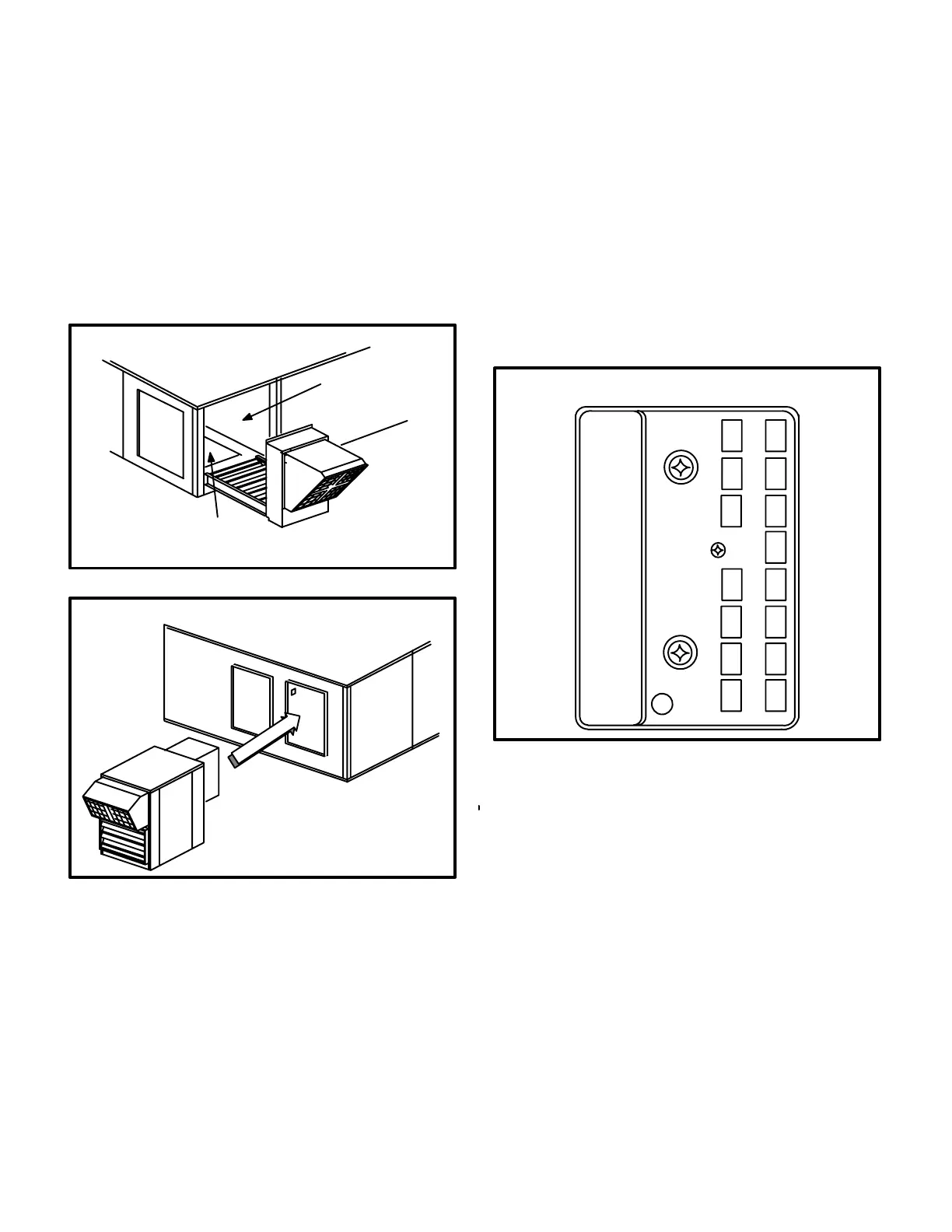
GCS16 cabinet. Figure 52 shows how an EMDH16
is installed in a GCS16 cabinet. For detailed installa
tion and maintenance instructions, refer to the
REMD16-41/65 Installation Instruction Manual or
the EMDH16-41/65 Installation Instruction Manu
al.
FIGURE 51
REMD16 INSTALLATION
BLOWER
COMPARTMENT
DOWNFLOW
RETURN AIR
OPENING
REMD16
or
REMD16M
FIGURE
52
EMDH16 INSTALLATION
UNIT
EMDH16
or
EMDH16M
f-Modulating Damper Motor Check
Honeywell W7459A
1- Disconnect main power to the GCS16.
2- Turn thermostat control to OFF position (oc
cupied mode).
3- Install jumper across terminals 6-9 on blower
relay in unit control box.
4- Install jumper across enthalpy control termi
nals T and T1. See figure 53 for terminal loca
tion.
5- Restore power to unit. Outdoor damper
should drive to fully open position (60 to 90
sec. required for full travel). Observe travel for
proper damper operation.
6- Disconnect power to the unit. Outdoor damp
er should spring return to closed position.
7- Remove T and T1 jumper then restore power to
the unit. Outdoor damper should drive to mini
mum position. Adjust minimum damper position
pot located on control. See figure 53.
8- Disconnect power to unit and remove jumper
on blower relay terminals 6-9. Replace all
panels. Restore power to unit.
FIGURE 53
MODULATING
SOLID STATE ENTHALPY CONTROL
TR TR1
A
BC
D
+
+
5
2
4
T1
P1P
T
1
MINIMUM
POSITIONER
LED
3
g-ThreePositionDamperMotorCheck
Honeywell W7459C
1- Disconnect main power to the GCS16.
2- Remove the control access cover (see figures
46 and 47).
3- Install jumper across enthalpy control termi
nals D and TR1. See figure 54 for terminal
location.
4- Restore power to unit. Outdoor damper
should drive to fully open position (requires
approximately 90 seconds for full travel). Ob
serve travel for proper damper operation.
5- Disconnect power to unit. Damper should
spring return to closed position.
6- Remove jumper installed in step 3. Install
jumper across enthalpy control terminals X
and TR1. See figure 54 for terminal location.

 Loading...