Page 52
F-LPG Kit
All A.G.A rated GCS16s are factory set for use with Natu
ral Gas. An optional L.P.G. conversion kit allows change
over from Natural to L.P.G. supply. The kit includes a gas
valve changeover kit, new gas orifice and either combus
tion air orifice or combustion air restrictor plate.
All C.G.A. rated GCS16s are factory set for use with Natu
ral or L.P. gases. Each unit must be ordered for the type of
gas to be used. Field changeover is not allowed.
Refer to the L.P.G. Conversion Kit Installation Instruction
for specific installation procedures.
WARNING - IMPROPER INSTALLATION, ADJUST
MENT, ALTERATION, SERVICE OR MAINTE
NANCE CAN CAUSE INJURY, PROPERTY DAM
AGE OR DEATH. CONSULT A QUALIFIED IN
STALLER, SERVICE AGENCY OR THE GAS SUP
PLIER FOR INFORMATION OR ASSISTANCE.
FIGURE 60
INLET
PRESSURE
TAP
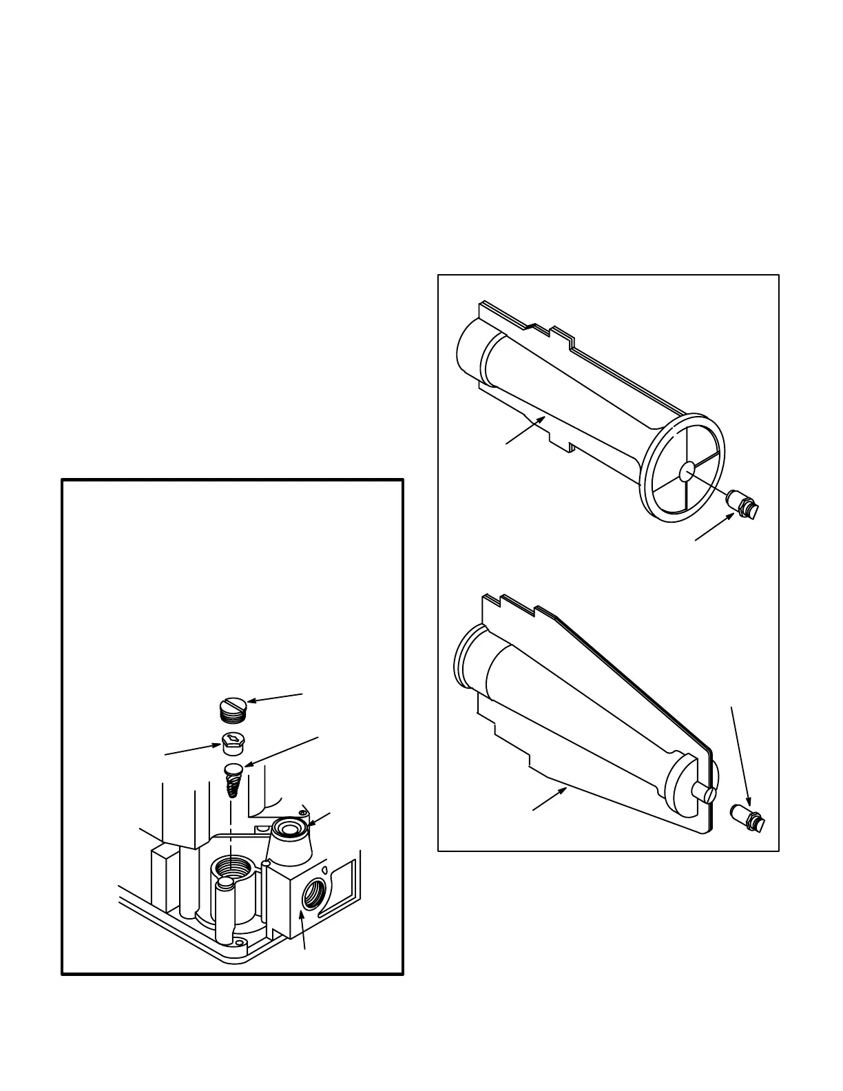
1. Remove regulator cap screw and pressure regulator adjusting
screw.
2. Remove existing spring.
3. Insert replacement spring with tapered end down.
4. Install the new plastic pressure regulator adjustment screw so
that the top of the screw is flush (level) with the top of the regula
tor. Turn the pressure regulator adjusting screw clockwise six
complete turns, This adjustment provides a preliminary pressure
setting of about 10" w.c. (2.5 kPa) for the LP regulator.
5. Check regulator setting either with a manometer or by clocking
the gas meter.
6. Install new cap screw.
CONVERSION OF HONEYWELL GAS
VALVE (Natural to LP)
CAPSCREW
(Black)
PRESSURE
REGULATOR
ADJUSTING
SCREW (White)
SPRING
Tapered End
Down (Red)
GAS INLET
All units which have been changed to L.P.G. operation
should be marked with a yellow sticker located near the
gas valve. Some of the components you may find in a unit
which has been converted to L.P.G. operation are listed
below. Do not use this information as an installation proce
dure.
L.P.G. conversion in all GCS16 units requires that the gas
valve be field converted and the burner orifice be changed.
Figure 60 shows gas valve conversion. Figure 61 shows
the orifice changeout.
FIGURE 61
INSTALLING LPG GAS ORIFICE
BURNER
ASSEMBLY
GAS ORIFICE
BURNER SLIDES ONTO ORIFICE.
ORIFICE IS THREADED INTO MANIFOLD.
BURNER
ASSEMBLY
GAS ORIFICE
100K and125K Btuh BURNER
50K and 75K Btuh BURNER
L.P.G. conversion of 50K Btuh heat exchangers requires a
new combustion air orifice. In GCS16H-50 units, the ori
fice is located between the combustion air blower and the
flue transition as shown in figure 62. In GCS16-50 and
GCS16R-50 units, the orifice is located outside the cabi
net between the outer mullion and the flue vent as shown
in figure 63.

 Loading...